Self-locking mechanism

A self-locking and assembly technology, applied in the direction of pliers, manufacturing tools, etc., can solve problems such as uneven movement, uneven lubricating oil coating, and uneven movement of the clamp 92

Inactive Publication Date: 2008-10-08
KINPO ELECTRONICS CHINA
View PDF4 Cites 0 Cited by
  • Summary
  • Abstract
  • Description
  • Claims
  • Application Information

AI Technical Summary

Problems solved by technology

[0006] However, in the above-mentioned method, manpower must be used to clamp the clamp 92 and apply lubricating oil on the long axis 911, but when manpower is used to apply force to the clamp 92, it will cause the problem of uneven force application, for example, If a certain part of the major axis 911 is too hard, the clamp 92 will be clamped, causing the clamp 92 to move less smoothly on this part of the major axis 911; otherwise, if the user applies too little force, it will cause clamping. Clamp 92 is too loose at a certain part of major axis 911
[0007] Therefore, the use of manpower to clamp the clamp 92 is likely to cause uneven force, and when the lubricating oil is applied, the movement will not be smooth, or the situation will be too loose, and thus the lubricating oil will be applied unevenly, so that it cannot be achieved. Not ideal for lubrication purposes

Method used


Image

  • Self-locking mechanism
  • Self-locking mechanism
  • Self-locking mechanism

Examples


Embodiment Construction

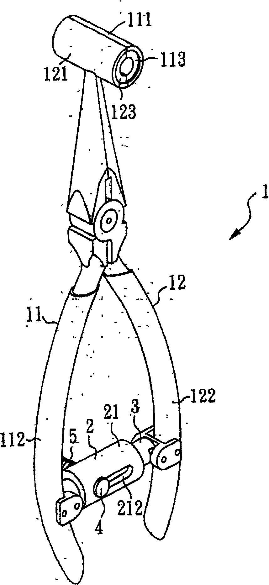
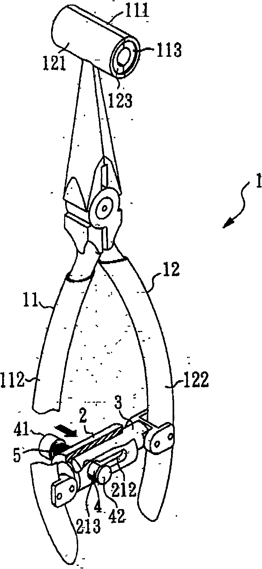
[0025] Please also see figure 1 is a perspective view of the present invention, and figure 2 It is an exploded view of the present invention, which shows a clamp 1, which includes a first half clamp 11 and a second half clamp 12, wherein the second half clamp 12 is the same as the first half clamp The tongs 11 are pivoted across each other, so that the first half tongs 11 and the second half tongs 12 can rotate relative to each other, and thus fulfill the function of the tongs 1 .

[0026] In addition, a first semicircle 111 is fixed at the front end of the first half clamp 11 of the clamp 1, and a second semicircle 121 is fixed at the front end of the second half clamp 12 of the clamp 1. The second semicircle 121 It is opposite to the first semicircle 111, and a first semicircle rubber cotton 113 is set in the first semicircle 111, and a second semicircle rubber cotton 123 is arranged in the second semicircle 121. Similarly, the second The semicircular rubber sponge 123 an...


PUM


Abstract

The invention discloses a self-locking accessory mechanism, which comprises the following parts: cylinder component, long axis component, movement shaft and spring component, wherein the cylinder component possesses mutual corresponding upper chute and lower chute; the long axis component is cased in the cylinder component, which pierces the expanding flute through-out hole corresponding to lower chute; the movement shaft pierces lower chute, through-out hole and upper chute, which consists of upper expanding part and lower expanding part; the lower expanding part corresponds to expanding flute; the spring component is cased on the movement shaft with top between upper expanding part and cylinder component, which provides elastic stress to move the movement shaft to be fixed in the expanding flute corresponding to lower expanding part.

Description

technical field [0001] The present invention relates to a self-locking mechanism, in particular to a self-locking mechanism for clamps that apply lubricating oil to shafts. Background technique [0002] For an electronic product generally having a long axis, such as an inkjet printer, an inkjet head is assembled on the long axis, and the inkjet head moves back and forth on the long axis to print desired text or pictures. [0003] The above-mentioned inkjet printers must be coated with lubricating oil on the long axis so that the inkjet head can move back and forth smoothly, and other electronic products with long axes must be coated with lubricating oil on the long axis if they have similar functions. The cloth is lubricated. [0004] Please refer to Fig. 5, which is a schematic diagram of a known inkjet printer coating lubricating oil, wherein an inkjet printer 91 is shown, and a major axis 911 is assembled in the inkjet printer 91, and a spray nozzle is assembled on the m...

Claims


Application Information

Patent Timeline
Patent Type & Authority Patents(China)
IPC IPC(8): B25B7/14
Inventor 陈忠贤
Owner KINPO ELECTRONICS CHINA
Why Eureka
Try Eureka