
Forced-convection asymmetrical radiator

A forced convection, asymmetric technology, applied in non-electron emitting anodes, non-electron emitting electrodes, magnetrons, etc., can solve the problems of lack of heat dissipation, rising product costs, increasing material usage, etc., to achieve savings The amount of use, the production process is simple, and the effect of reducing costs

Inactive Publication Date: 2008-04-30
UNIV OF ELECTRONICS SCI & TECH OF CHINA
View PDF6 Cites 0 Cited by
  • Summary
  • Abstract
  • Description
  • Claims
  • Application Information

AI Technical Summary

Problems solved by technology

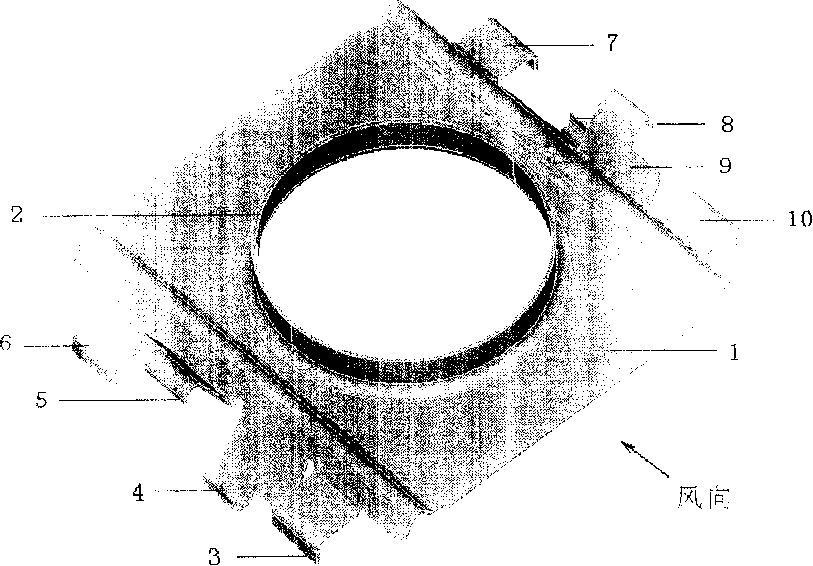
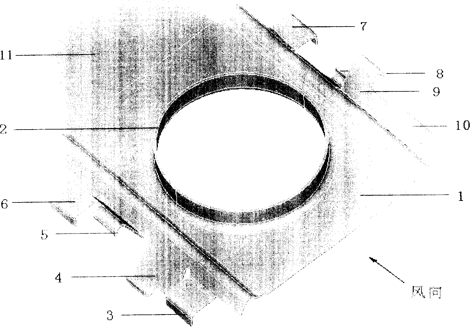
figure 2 The symmetrical heat sink shown in includes: 1 main fin, 2 fixed rings, 3 to 10 are the first to eighth secondary fins, from figure 2 It can be seen that the structure of this existing heat sink is symmetrical, that is, the anode of the magnetron is located at the center of the main fin of the heat sink; image 3 shown), image 3 The extended heat sink shown in includes: 1 main wing, 2 fixed rings, 3 to 10 are the first to eighth secondary fins, and 11 is the tail fin; the magnetron anode is still located in the center of the main fin of the heat sink, but in Tail fins are added to the air outlet to increase the heat dissipation effect; although this heat sink improves the heat dissipation efficiency, it increases the amount of materials used and increases the cost of the product
None of them do the best heat dissipation with less material

Method used


Image

  • Forced-convection asymmetrical radiator
  • Forced-convection asymmetrical radiator
  • Forced-convection asymmetrical radiator

Examples


Embodiment Construction

[0030] The present invention will be described more clearly below through detailed embodiments and with reference to the accompanying drawings.

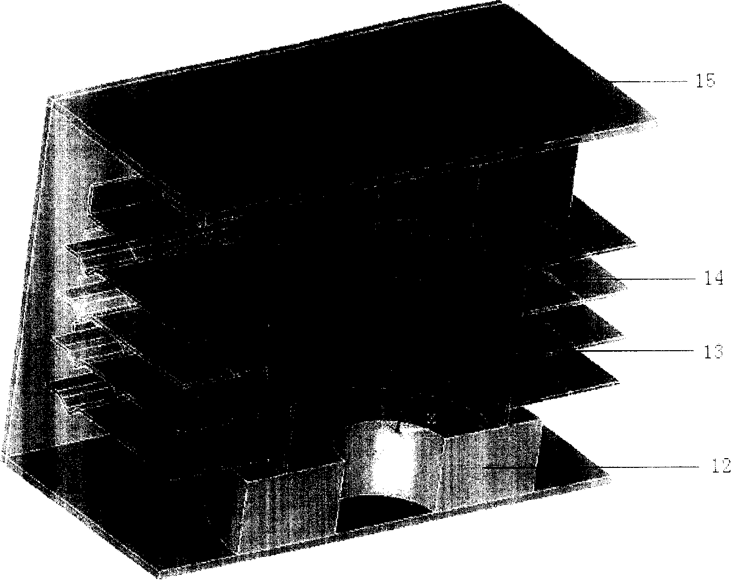
[0031] The numerical simulation calculation of the temperature field distribution of the 2M217 magnetron under forced convection shows that the maximum temperature of the central anode is 123°C ( Figure 5 The dotted line range in the middle), cut off the heat sink at the air inlet by 9mm and then calculate, the maximum temperature of the central anode after cutting off is 116°C ( Figure 5 The dashed range in ). It can be seen from this example that the present invention is simple and easy to implement, saves materials and reduces costs while ensuring the same heat dissipation effect.


PUM


Abstract

The invention discloses a dissymmetrical radiator under compelling convection. It uses the feature that the temperature field is dissymmetrical while compelling convection. Cutting off a certain wideness of the main fan in existence at the wind entrance, and keep the original size at the wind exit. Thus, the magnetron anode is in the dissymmetrical location relative to the main fan. It is easy to produce and need not to change the product line and process. The invention can not only used for magnetron heat emission, but also used as the other radiator under compelling convection.

Description

Technical field: [0001] The invention belongs to the fields of electronic technology and heat dissipation technology, and in particular relates to the technology that a magnetron utilizes heat dissipation fins to enhance heat dissipation. Background technique: [0002] Magnetron is a high-power microwave source with the highest efficiency. It is characterized by high output power, high efficiency, small size, light weight and low cost. Therefore, it has been widely used not only in the military field, but also in the civilian field. has been well applied. With the development of radar, aerospace, electronic countermeasures, microwave heating and other technologies, higher requirements are put forward for magnetrons. When the magnetron is working, its anode temperature mainly comes from three aspects: the radiation from the hot cathode surface, the bombardment of electrons on the anode blades, and the eddy current generated by the high-frequency current flowing along the ano...

Claims


Application Information

Patent Timeline
Patent Type & Authority Patents(China)
IPC IPC(8): H01J19/36H01J25/50
Inventor 姚列明杨中海曾葆青
Owner UNIV OF ELECTRONICS SCI & TECH OF CHINA
Learn More