
Piston type energy accumulator

An accumulator and piston-type technology, which is applied in the field of hydraulic control, can solve problems affecting the normal use of piston-type accumulators, shorten the gas supplementary pressure cycle, and reduce system reliability, so as to achieve convenient installation and set-up, and solve internal leakage problems , the effect of simple structure

Active Publication Date: 2008-03-26
SANY HEAVY IND CO LTD (CN)
View PDF7 Cites 6 Cited by
  • Summary
  • Abstract
  • Description
  • Claims
  • Application Information

AI Technical Summary

Problems solved by technology

Both kinds of leakage will cause the pressure of the air cavity to drop, so that the accumulator needs to be frequently inflated and replenished, which shortens the gas replenishment cycle, increases the cost of use, and reduces the reliability of the system, which affects the normal use of the piston accumulator

Method used


Image

  • Piston type energy accumulator
  • Piston type energy accumulator
  • Piston type energy accumulator

Examples


Embodiment Construction

[0024] The present invention will be described in further detail below in conjunction with the accompanying drawings and specific embodiments.

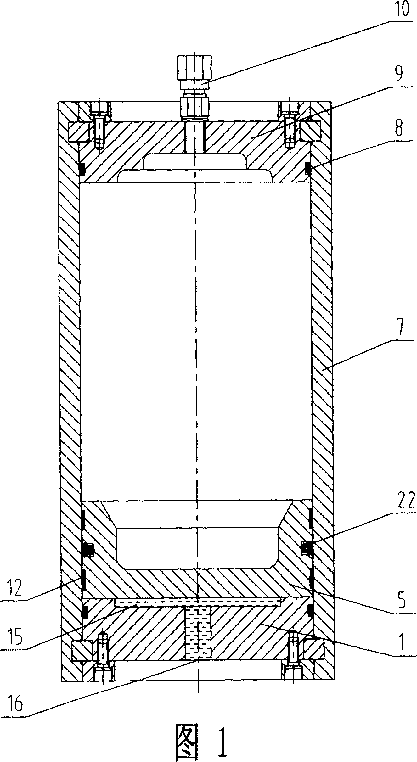
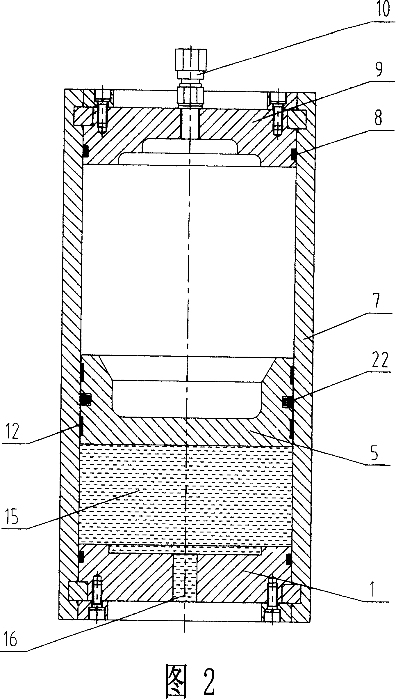
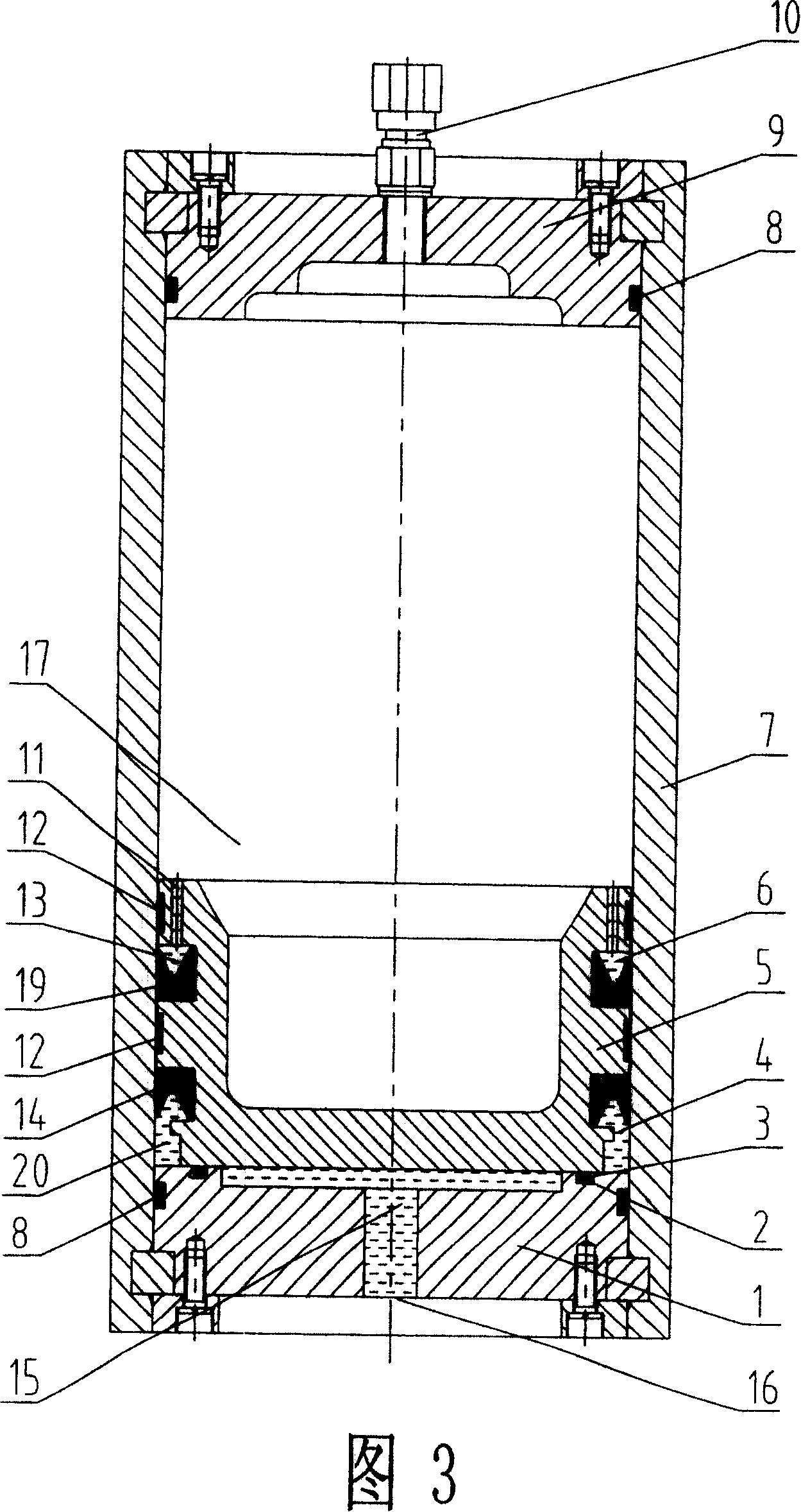
[0025] As shown in Fig. 3 and Fig. 4, the piston accumulator of the present invention includes a cylinder 7, a gas cover 9, a piston 5, an end cover 1 and an inflation valve 10 connected to the gas cover 9, and the piston 5 is provided with The guide ring 12, the end cover 1 and the gas cover 9 are all provided with a fourth sealing ring 8 for radial sealing. The gas cover 9 is fixed on the top of the cylinder 7, the end cover 1 is fixed on the bottom of the cylinder 7, the piston 5 is located between the gas cover 9 and the end cover 1 and the cylinder 7 is divided into an air chamber 17 and an oil chamber 15, and the piston 5 A first annular groove 4 is formed between the end close to the end cover 1 and the inner wall of the cylinder barrel 7, and a first sealing ring 14 is installed in the first annular groove 4; when the first an...


PUM


Abstract

The present invention discloses a kind of piston energy storage device. It includes the following several portions: cylinder, cylinder cap, piston, end cover and charging valve connected on the cylinder cap. The described cylinder cap is fixed on the top end of the cylinder, the end cover is fixed in bottom end of said cylinder, said piston is positioned between cylinder cap and end cover and can be used for dividing the cylinder interior into air cavity and oil cavity. It is characterized by that between the end portion of piston closed to the end cover and inner wall of said cylinder a ring groove is formed, in said ring groove, a sealing ring is mounted.

Description

technical field [0001] The invention mainly relates to the field of hydraulic control, in particular to a piston type accumulator. Background technique [0002] The piston accumulator is a commonly used isolated hydraulic energy storage device in the hydraulic system. Its function is to stabilize the system pressure, and the second is to store the energy in the system and release it again when needed. Its working principle is: the piston separates the cylinder into two parts, the upper part is pre-filled with a certain pressure of gas, and the lower part communicates with the hydraulic oil circuit through the oil port. When the system oil pressure rises, the hydraulic oil pushes the piston upward to compress the gas, and the gas pressure rises. When the gas pressure is balanced with the system oil pressure, the piston stops moving, and the accumulator completes the liquid filling stage; when the system oil pressure decreases, The gas pressure is higher than the oil pressure...

Claims


Application Information

Patent Timeline
Patent Type & Authority Patents(China)
IPC IPC(8): F15B1/24
CPCY02E60/15Y02E60/16
Inventor 易小刚刘震洲
Owner SANY HEAVY IND CO LTD (CN)
Learn More