Adjustable sealing structure of regulating valve

A sealing structure and adjustable technology, applied in the field of regulating valves, can solve the problems of external leakage or internal leakage, low production efficiency of regulating valves, etc., and achieve the effect of reducing manufacturing costs

Active Publication Date: 2022-02-22
ZHEJIANG YONGSHENG TECH CO LTD
View PDF7 Cites 0 Cited by
  • Summary
  • Abstract
  • Description
  • Claims
  • Application Information

AI Technical Summary

Problems solved by technology

[0005] The first purpose of the present invention is to provide a cage-type control valve that can effectively solve the problem of low production efficiency of the control valve due to repeated positioning and external leakage or internal leakage due to inaccurate parts size repair. Problems, in order to achieve the adjustable sealing structure of the regulating valve that reduces the manufacturer's manufacturing cost and the user's maintenance cost
[0006] Another purpose of the present invention on the basis of the first purpose is to provide a control valve that can effectively solve the problem of external leakage or internal leakage of the existing cage control valve due to thermal expansion and contraction of the cage. Adjustable sealing structure

Method used


Image

  • Adjustable sealing structure of regulating valve
  • Adjustable sealing structure of regulating valve
  • Adjustable sealing structure of regulating valve

Examples


specific Embodiment 1

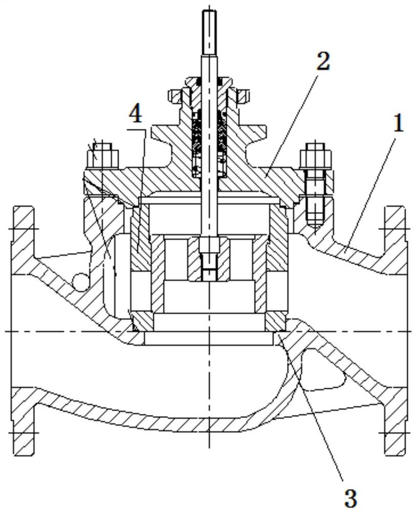
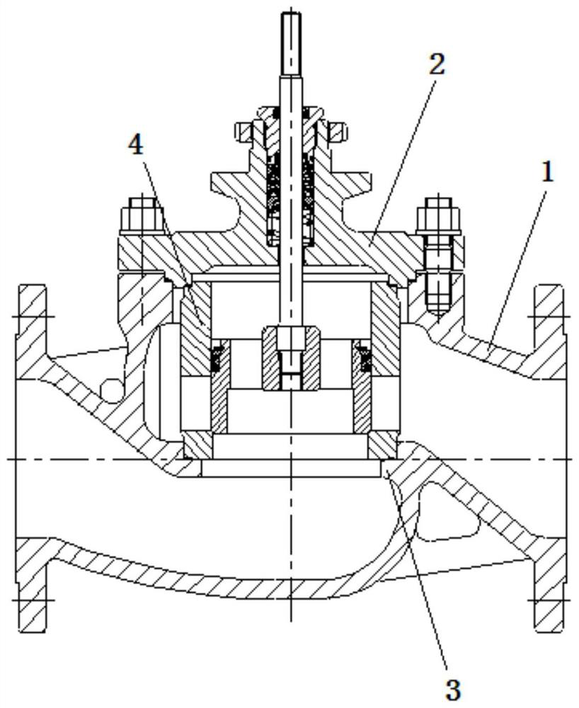
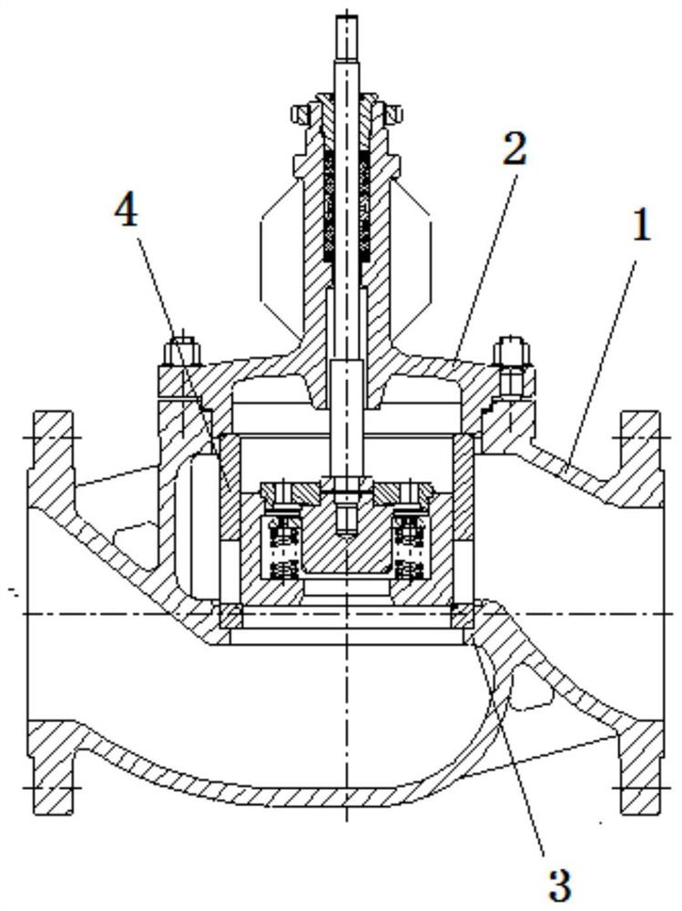
[0047] Specific embodiment one: as Figure 5 , Image 6 , Figure 7 As shown, an adjustable sealing structure of a regulating valve includes a valve body 1, a valve cover 2, a valve seat 3 located in the valve body, a cage 4 located in the valve body, and a sealing adjustment mechanism 5. A valve cover sealing gasket 7 is arranged between the valve body and the valve cover. In this embodiment, the valve body and the valve cover are connected by bolts, and the valve cover sealing gasket between the valve cover and the valve body is pressed by tightening the bolts connecting the valve cover and the valve body to achieve the valve cover and the valve body. The seal between the valve seats. A valve seat sealing gasket 6 is arranged between the lower end of the valve cage and the valve seat. The sealing adjustment mechanism 5 includes a top ring 5.0 located between the bonnet and the upper end of the cage, a threaded hole arranged on the bonnet, an adjusting screw 5.1 matched ...

specific Embodiment 2

[0055] Specific embodiment two: the specific structure of this embodiment is with reference to specific embodiment one, and its difference is:

[0056] Such as Figure 8 As shown, the inner edge of the top ring 5.0 is provided with a blocking sleeve 5.5 extending downward, and the lower end of the blocking sleeve extends downward into the valve cage. The gap between the outer surface of the blocking sleeve and the inner surface of the cage is smaller than the set value. In this embodiment, the gap between the outer surface of the blocking sleeve and the inner surface of the cage is 0.1 mm or 0.2 mm or 0.3 mm. The blocking sleeve is used to block the gravel in the water from entering the preset gap.

[0057] Since there may be sand and stones in the water, during the use of the control valve, once the sand and stones in the water enter the preset gap, the axial deformation of the cage due to thermal expansion and contraction will not be effectively absorbed by the elastic elem...


PUM


Abstract

The invention discloses an adjustable sealing structure of a control valve, aiming to provide a method that can effectively solve the problems of the existing cage control valve due to repeated positioning, which causes low production efficiency of the control valve and inaccurate size repair of parts. And the adjustable sealing structure that causes the problem of external leakage or internal leakage. It includes a valve body, a valve cover, a valve seat located in the valve body, a valve cage located in the valve body and a sealing adjustment mechanism. A valve seat sealing gasket is provided between the lower end of the valve cage and the valve seat. The sealing adjustment mechanism It includes a top ring between the bonnet and the upper end of the cage, a threaded hole arranged on the bonnet, an adjusting screw matched with the threaded hole, and a lock nut arranged on the adjusting screw and outside the bonnet, the top ring The top ring is in sealing connection with the valve cover, and the top ring is in sealing connection with the valve cage, and the end of the adjusting screw abuts against the top ring, so that the valve cage presses the sealing gasket of the valve seat.

Description

technical field [0001] The invention relates to a regulating valve, in particular to an adjustable sealing structure of the regulating valve. Background technique [0002] Straight stroke regulating valve is a kind of regulating valve with a large number of supporting installations in various processes and processes. Generally, most of these valves are in continuous working state, that is, after the system is opened, the valve continuously controls the system medium. The valve will stop using during the cycle; during the operation of the system, it is not expected that the valve will have failures that affect continuous production, especially internal leakage, external leakage and other conditions. The spool structure of the straight stroke regulating valve can be divided into single-seat plunger type, cage single-seat type, cage type double-seat type, cage type single-seat pre-opening type, etc. Among them, the cage type regulating valve has a small unbalanced force , The ...

Claims


Application Information

Patent Timeline
Patent Type & Authority Patents(China)
IPC IPC(8): F16K3/26F16K3/30F16K3/314
CPCF16K3/26F16K3/30F16K3/314
Inventor 杨熙翀
Owner ZHEJIANG YONGSHENG TECH CO LTD
Why Eureka
Try Eureka