
Moving iron (electromagnetism system) type AC ammeter, voltmeter

An alternating current, moving iron technology, applied to moving iron musical instruments, etc., can solve the problems of users' economic losses, magnetic performance reduction, and working accuracy reduction, and achieve the effects of reducing product costs, simplifying intermediate processes, and improving accuracy

Inactive Publication Date: 2008-02-27
秦永仁
View PDF7 Cites 0 Cited by
  • Summary
  • Abstract
  • Description
  • Claims
  • Application Information

AI Technical Summary

Problems solved by technology

There is a prominent problem with this magnetic core structure, that is, once the magnetic field strength of the permanent magnet is magnetized by the magnetizer, its field strength cannot be adjusted manually. After a long time, there will be a slight magnetic flux leakage and the magnetic performance will be reduced.
In particular, when the aging of the crystal element used in the electrical instrument or due to vibration and other reasons will affect the change in the position of the moving coil in the magnetic gap, even if the change is very small, it is impossible to ensure the consistency of high precision, thus The uniformity of the magnetic field is changed, which affects the working accuracy of the instrument
In addition, after the magnetic core is installed in the instrument and leaves the factory, its performance and parameters have been fixed. However, after the user uses it for a period of time, the characteristics of the magnet itself will be changed (demagnetization) due to the influence of time, environment and working temperature. , so that the working accuracy of the watch is significantly reduced. At this time, the magnetic field strength generated by the magnetic core cannot be manually adjusted, and sometimes the entire watch has to be scrapped, which brings undue economic losses to the user.

Method used

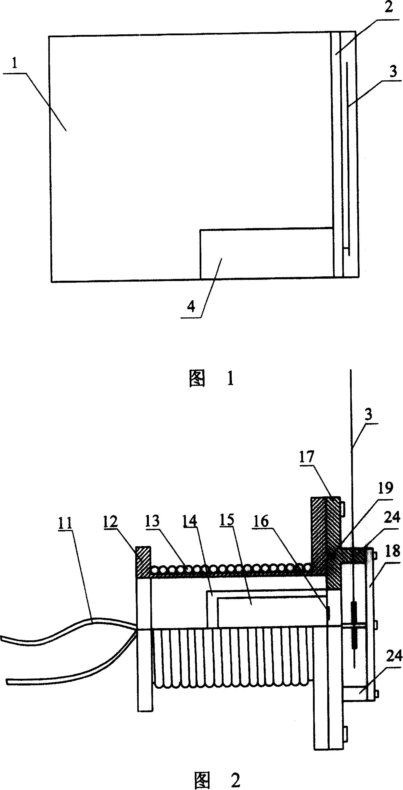

Image

  • Moving iron (electromagnetism system) type AC ammeter, voltmeter
  • Moving iron (electromagnetism system) type AC ammeter, voltmeter

Examples


Embodiment Construction

[0016] The technical solutions of the present invention will be further specifically described below through the embodiments and in conjunction with the accompanying drawings.

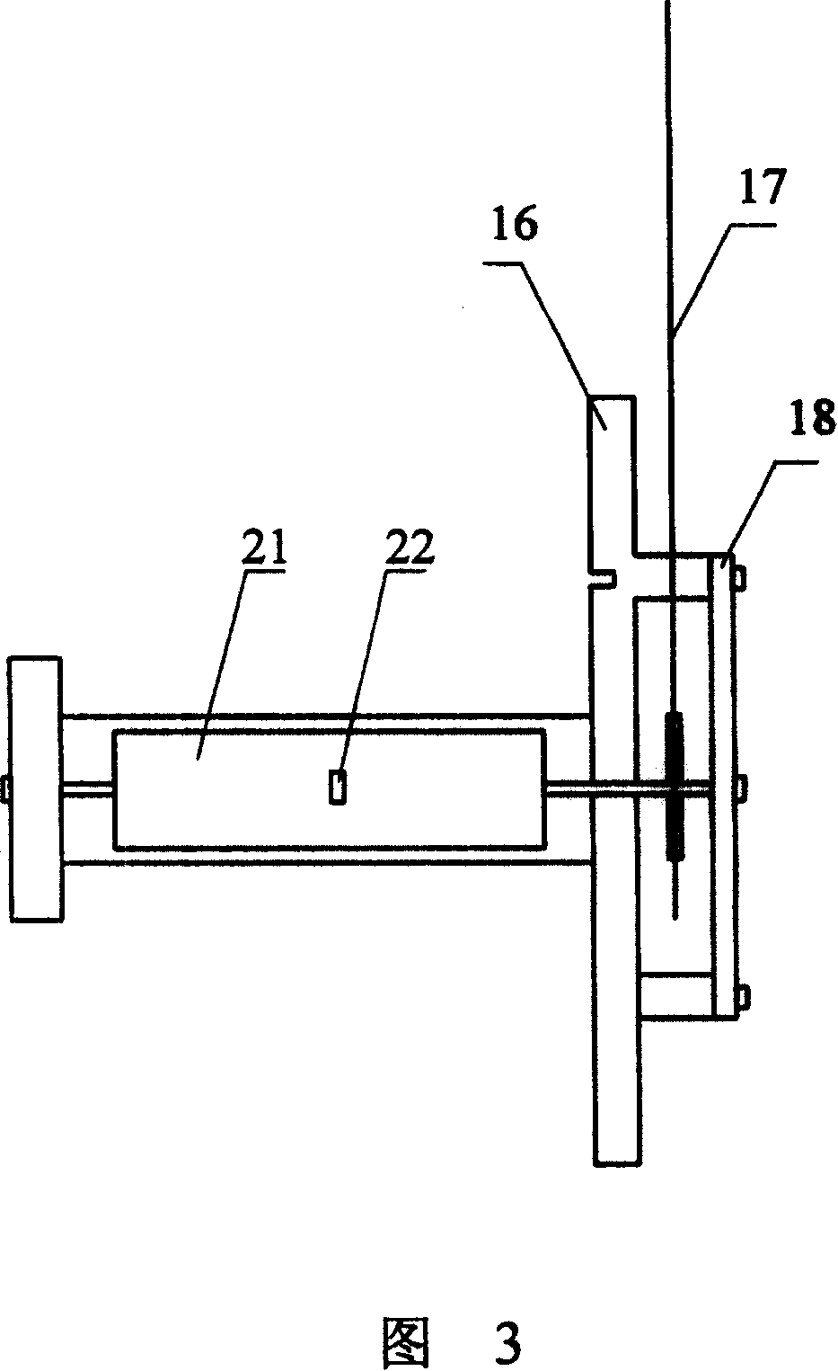
[0017] The improved electromagnetic meter of the present invention is shown in Figure 1 and Figure 2, wherein the electromagnetic movement device can be assembled into an electromagnetic meter with a case 1, a dial 2 and a pointer 3, which greatly simplifies the structure of the meter. The electromagnetic core device comprises a cylindrical coil support 12, the coil support 12 is shaped on a coil 13, the hollow part of the coil support 12 is provided with a static piece 15, a moving piece 21 and a rotating shaft support 17, the rotating shaft and the coil on the rotating shaft support 17 The bracket 12 is arranged concentrically, wherein the static piece 15 and the static piece bracket 14 are fixed together and then embedded on the inner wall of the hollow part of the coil bracket 12 , and the moving pi...


PUM


Abstract

The invention discloses a moving iron (electromagnetic type) AC current / voltage meter, comprising: a meter casing, a meter dial, a pointer and an electromagnetic movement for driving the pointer, where the electromagnetic movement is a coil bracket wound with a coil, one end of the coil bracket is fixed with a rotating shaft bracket, the hollow inner wall of the coil bracket is provided with a stator bracket fixed with a stator, the rotating shaft extending into the hollow part of the coil bracket is provided with a rotor, and the stator and rotor match. The invention omits a transformer and a circuit connected with it, reducing bulk and improved into a flow of power input-induction coil-magnetic repulsion-point deflection. And the meter dials can be unitedly printed without manual regulation, thus raising accuracy and sensitivity and reducing product cost.

Description

technical field [0001] The invention relates to the field of electrical instruments and meters, in particular to an electromagnetic moving iron AC current and voltmeter with improved structures such as an electromagnetic movement device in an electromagnetic instrument. Background technique [0002] The structure and principle of the widely used magnetoelectric instrument have been known for a long time, and have been widely used in industry. For the magnetoelectric instruments produced by instrument manufacturers at home and abroad, the core structure of the movement part - the magnetic core, is to set a permanent magnet (generally a rectangular or square magnet) in the magnetic cylinder, and add two garden columns The missing-shaped magnetic conductor makes it form a cylindrical magnetic core structure, and maintains an equidistant gap with the inner diameter of the magnetic permeable cylinder, so that the gap forms a uniform magnetic field gap. In this way, when a curren...

Claims


Application Information

Patent Timeline
Patent Type & Authority Patents(China)
IPC IPC(8): G01R5/14
Inventor 秦永仁瞿金桂
Owner 秦永仁
Learn More