High-voltage network high-capacity powerfree compensation continuous regulation method

A high-voltage power grid and adjustment method technology, applied in reactive power compensation, reactive power adjustment/elimination/compensation, etc., can solve the problems of power grid impact, large economic losses, and inability to continuously adjust, so as to avoid impact and prolong working life. Effect

Inactive Publication Date: 2008-02-06
SHANGHAI JIAO TONG UNIV
View PDF4 Cites 0 Cited by
  • Summary
  • Abstract
  • Description
  • Claims
  • Application Information

AI Technical Summary

Problems solved by technology

[0006] 1) Capacitor cut-off of large-capacity reactive power compensation device of high-voltage power grid is carried out in stages. Since the cost of switch-over switch in high-voltage system is very high, the number of stages cannot be too many, and the steps are all above 1000kVar. It is necessary to increase or decrease more than 1000kVar, so that the power system is still often in the state of overcompensation or undercompensation
Due to the inability to continuously adjust the reactive power of many enterprises, the economic loss of fines due to reactive power exceeding the standard is very large
[0007] 2) When the capacitor is switched on, the impact current is very large, which not only causes an impact on the power grid, but also greatly affects the life of the capacitor and the switching switch
[0008] 3) In places where reactive power changes frequently, the service life of the cut-and-throw switch is far from meeting the actual needs
Taking an electrified railway as an example, whenever a locomotive passes a certain section, reactive power compensation must be carried out, so that the number of capacitor cut-offs can be as high as 600 times / day, and a large current passes through the switch when switching, so that the switch lifespan has become a problem that cannot be solved for a long time
[0009] 4) Although the use of solid-state switches can solve the impact of current, it has high cost and large power consumption in high-voltage systems. Although the adjustment of its conduction angle can continuously adjust the reactive power, it brings serious harmonics to the power system. wave pollution
[0014] In the high-voltage power grid, the capacity of the reactive power compensation device required by the system is very large, generally at the Mvar level, for example, if Q=6Mvar, the capacity of the variable voltage source Qv=1500KVA, and the corresponding device cost is very high.

Method used


Image

  • High-voltage network high-capacity powerfree compensation continuous regulation method

Examples


Embodiment Construction

[0029] In order to better understand the technical solution of the present invention, the technical solution of the present invention will be further described in detail below in conjunction with the accompanying drawings and embodiments.

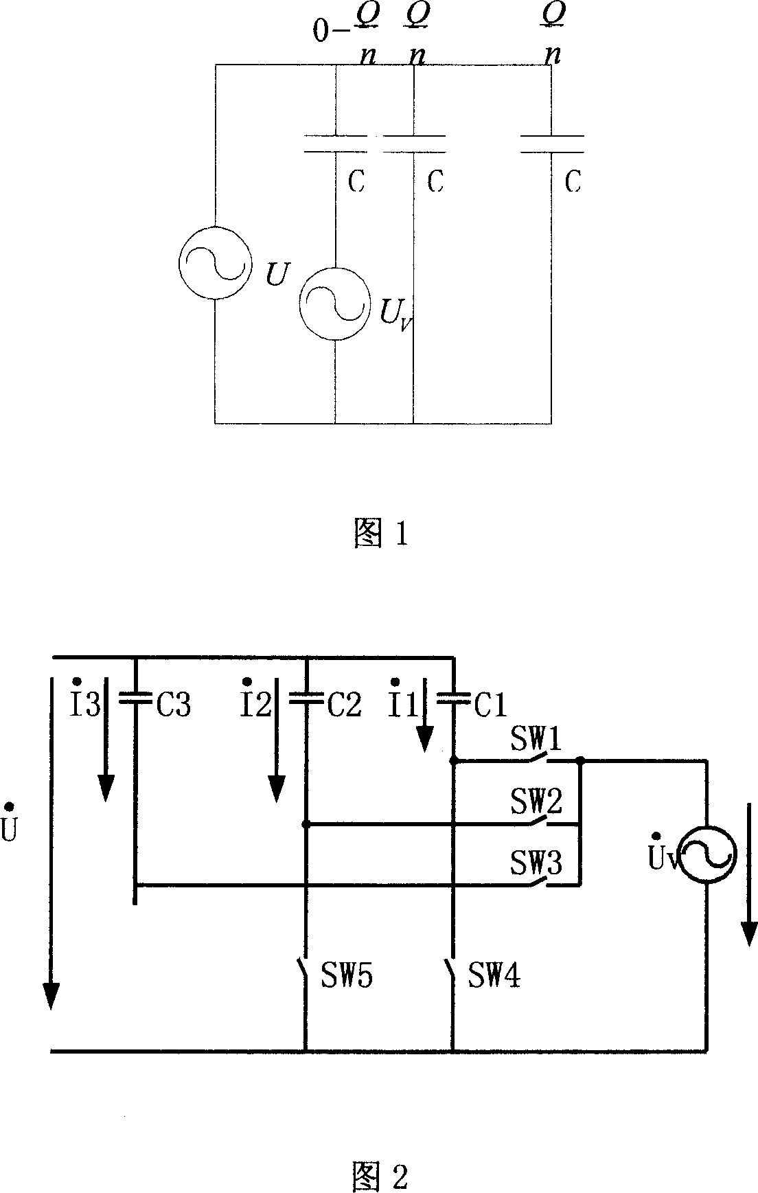
[0030] The principle of the present invention to realize the continuous adjustment of reactive power compensation is shown in Figure 1. The large-capacity reactive power compensation continuous adjustment circuit of the high-voltage power grid is composed of n reactive power compensation branches, and one of the compensation branches connects the fixed capacitor C and the variable voltage source u V connected to provide 0-Q / n continuously regulated reactive power, while the other n-1 compensation branches connect the fixed capacitor C to the power supply U to provide fixed reactive power Q / n, by compensating the first The continuous adjustment of the branch and the switching of other compensation branches can realize the continuous adjustme...


PUM


Abstract

Provided total reactive power Q requested by system is supplied by n pieces of reactive compensation branch. A fixed capacitor is connected to a variable voltage source in one piece of compensation branch to supply 0-Q / n continuous controlled reactive power. Other n-1 pieces of compensation branch connect fixed capacitor to power source to supply fixed reactive powers. System reactive power is continuous controlled from 0-Q by continuous controlling reactive power in first piece of compensation branch and switching to other compensation branches. The capacity Qv of variable voltage source is only 1 / 4n of Q. Switching operation is implemented at time of zero current of all capacitors in n pieces of reactive compensation branch in order to avoid impulsion from electric network. Features are: low cost to realize reactive continuous control for electric network in high voltage, and prolonging service life of capacitor and switches.

Description

technical field [0001] The invention relates to a large-capacity reactive power compensation continuous adjustment method for a high-voltage power grid, which can be used for reactive power compensation of a 6KV and above power grid, and belongs to the technical field of electric power systems. Background technique: [0002] At present, the main methods of reactive power compensation for 6KV and above power grids at home and abroad are as follows: [0003] 1) Provide capacitive reactive power for the power system through capacitor switching to improve the power factor of the power supply system. [0004] 2) By adjusting the conduction angle of the thyristor, the magnitude of the current passing through the inductor can be changed, and the size of the inductive reactive power can be adjusted to maintain the stability of the grid voltage. [0005] But this traditional method has the following outstanding problems: [0006] 1) Capacitor switching of large-capacity reactive po...

Claims


Application Information

Patent Timeline
Patent Type & Authority Patents(China)
IPC IPC(8): H02J3/18
CPCY02E40/30
Inventor 叶芃生郑益慧凌志斌
Owner SHANGHAI JIAO TONG UNIV
Why Eureka
Try Eureka