


Quick Research
Generate reliable direction feasibility study reports for your R&D in just a few steps.

Technical Q&A
Discover and master advanced knowledge NOW. Basics, ideas, possibilities, all at once.

Find Solutions
As an expert in R&D theories, this can generate solutions to your technical problems instantly.

Evaluate Feasibility
Analyze your overall solution with one click, know your potential R&D risks in advance.

Monitor Landscape
Get weekly tech updates, stay abreast of the latest tech innovations and key insights.
Composite material
A technology of composite materials and substrates, which can be used in thin material processing, application, coating, etc., and can solve problems such as decreased hydrophilicity
- Summary
- Abstract
- Description
- Claims
- Application Information
AI Technical Summary
Problems solved by technology
Method used
Image

Examples
Embodiment approach 1
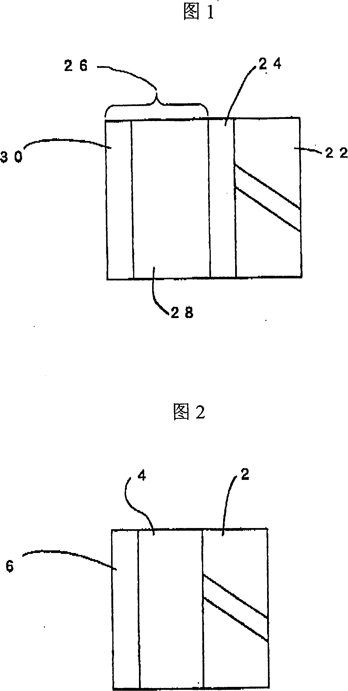
[0062] Fig. 1 is a cross-sectional view of Embodiment 1 of the anti-fog material of the present invention. On the surface of a light-transmitting plate material 22 such as resin or glass, films such as Cr and Rh are formed by vacuum coating or sputtering. 24. On the surface of the transparent metal film 24, a hydrophilic functional layer 26 containing a photocatalytic substance is provided. The hydrophilic functional layer 26 that contains photocatalytic substance is from the side of transparent metal film 24, will contain TiO 2 Photocatalytic layer 28 of photocatalytic substances such as SiO 2 The hydrophilic layer 30 of a hydrophilic material such as a vacuum coating method or a method such as sputtering is laminated to form a film. In the present embodiment, in order to increase hydrophilicity, it is preferable to form a porous state on the surface of the hydrophilic layer 30 containing a hydrophilic substance.
[0063] Prepare the transparent metal thin film 24 in the st...
Embodiment approach 2
[0082] 10 is a cross-sectional view showing Embodiment 2 of the composite material of the present invention. On the surface of the light-transmitting plate material 22, transparent metal films 24 such as Cr and Rh are used to form a film by vacuum coating, and then the transparent metal film 24 is formed into a film. Surface, adopt vacuum coating method or sputtering method to form TiO 2 etc. The film 32 of the hydrophilic layer of the photocatalytic substance.
[0083] Because TiO 2 The photocatalytic substance such as is excited by light and produces hydrophilicity, in embodiment 2, because the hydrophilic layer 32 of photocatalytic substance is made of having TiO 2 Such a hydrophilic photocatalytic substance is formed, the surface of the material is hydrophilized, and the hydrophilicity can be maintained by photocatalytic decomposition. Furthermore, in the present embodiment, in order to increase hydrophilicity, it is preferable that the surface of the photocatalytic subs...
Embodiment approach 3
[0085] Fig. 11 is a cross-sectional view showing Embodiment 3 of the composite material of the present invention. On the surface of the light-transmitting plate material 22, transparent metal films 24 such as Cr and Rh are used to form a film, and then on the surface of the transparent metal film 24, vacuum coating is used. method to form TiO-containing 2 and other photocatalytic substances and SiO 2 A hydrophilic substance mixed layer 34 such as a photocatalytic substance and the like is formed into a film, and it is preferable to form a porous state on the surface of the mixed layer 34 containing a photocatalytic substance and a hydrophilic substance.
[0086] In the structure shown in FIG. 11, since the mixed layer 34 containing the photocatalytic substance and the hydrophilic substance is formed, the surface of the material is hydrophilized, and the hydrophilicity can be maintained by photocatalytic decomposition.
[0087] In addition, on the back of the light-transmittin...
PUM
| Property | Measurement | Unit |
|---|---|---|
| Thickness | aaaaa | aaaaa |
| Thickness | aaaaa | aaaaa |
| Thickness | aaaaa | aaaaa |
Abstract
Description
Claims
Application Information
 - R&D Engineer
- R&D Manager
- IP Professional
- Industry Leading Data Capabilities
- Powerful AI technology
- Patent DNA Extraction
Browse by: Latest US Patents, China's latest patents, Technical Efficacy Thesaurus, Application Domain, Technology Topic, Popular Technical Reports.
© 2024 PatSnap. All rights reserved.Legal|Privacy policy|Modern Slavery Act Transparency Statement|Sitemap|About US| Contact US: help@patsnap.com