
Thread spraying structure

A technology of spinning and spinneret, which is applied in the field of spinning, and can solve the problems of increasing safety accidents, being unable to be carried away by other filaments, and broken filaments.

Inactive Publication Date: 2008-01-09
CHANGSHU XIANGYING SPECIAL FIBER
View PDF3 Cites 0 Cited by
  • Summary
  • Abstract
  • Description
  • Claims
  • Application Information

AI Technical Summary

Problems solved by technology

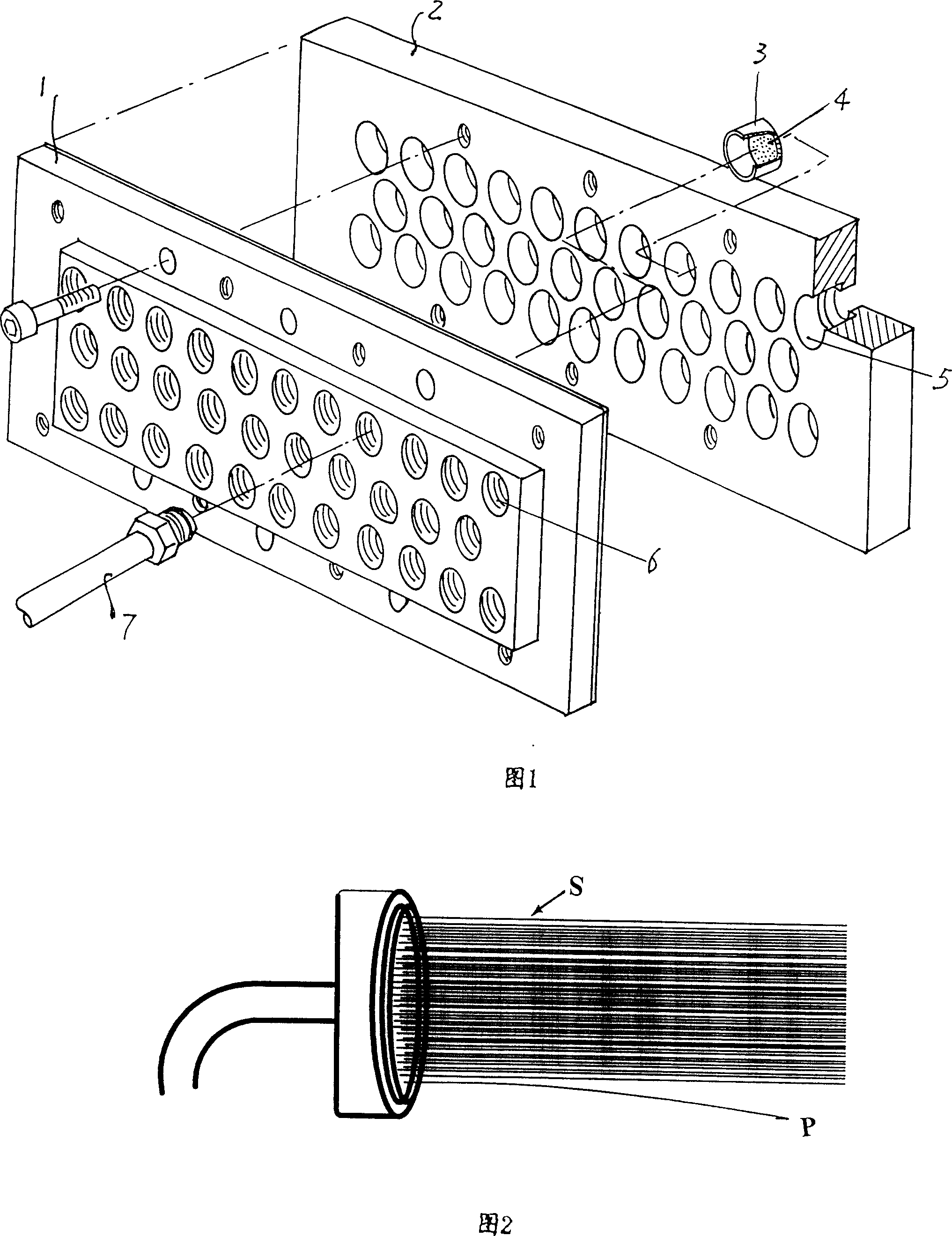
It can be seen from the above structure that because the spinneret 3 is fixed on the spinneret seat cavity 5, the spinneret 3 is static, and the filament bundles ejected during the spinning process do not have cohesive force, so broken filaments can't be carried away
Especially in the filament production process, because the number of filaments in the tow is relatively small, so the cohesion is very poor, and the broken filaments can hardly be entrained away, and the floating filaments will be wrapped around the rollers to form entanglements. rolls, which affect the smooth operation of the production line, resulting in low output and unguaranteed quality; in addition, the winding rolls need to be handled manually by the operator, which greatly increases the probability of safety accidents. In fact, safety accidents in the chemical fiber production industry mainly occur in the processing of winding roll in process
[0005] The defects exposed by the spinning mechanism in the prior art during the spinning process can be revealed by the enlarged Figure 2. This figure is based on a spinneret 1 with only one spinneret 3 as an example. Apparently, there is no cohesion between the thousands of primary fibers S ejected from the thousands of extremely fine spinneret holes 4 on the spinneret 3. When broken filaments P When, it cannot be carried away by other wires, it will be wound on the roller to form a roll
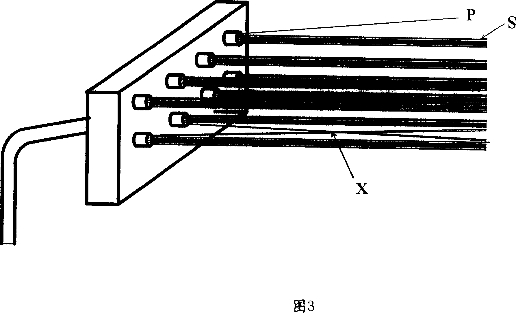
[0006] It can also be revealed by Fig. 3 that the tens to hundreds of primary fibers (filaments) S ejected from the tens to hundreds of tiny spinneret holes 4 on the spinneret 3 are embracing because the tow is small. The resultant force is even worse, and cannot be entrained when a broken filament P occurs. In addition to the above-mentioned disadvantages of winding rolls, due to the poor cohesion force, it will also be sprayed from different or adjacent spinneret 3 spinneret holes 4. The primary fibers S are entangled with each other, resulting in cross-interference entangled filaments X, which makes it difficult to separate the filaments

Method used


Image

  • Thread spraying structure
  • Thread spraying structure
  • Thread spraying structure

Examples


Embodiment Construction

[0037] The examples described below are convenient for understanding the spinning mechanism of the present invention but do not limit the content of the present invention.

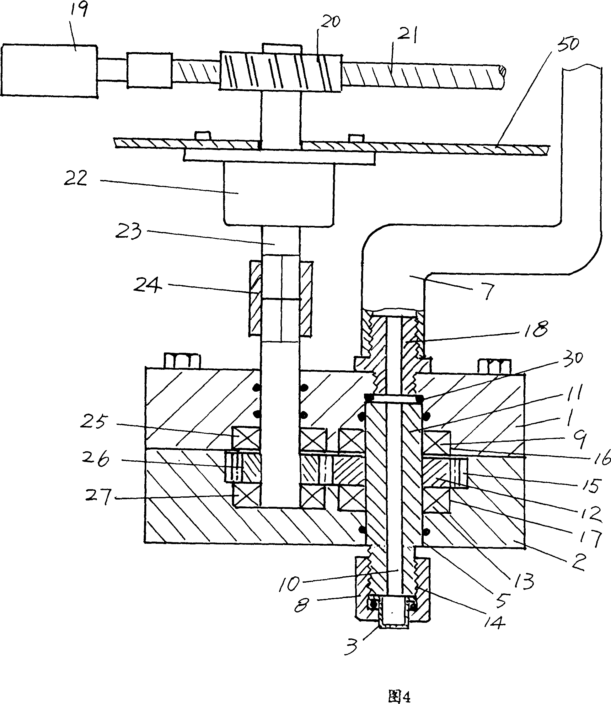
[0038] In Fig. 4, this figure is the form that the applicant exemplifies and is suitable for a single spinneret 3, because the spinneret mechanism only includes a spinneret 3, so the rotating device also only has one set, and the sprayer of this structure The wire mechanism does not need to adopt the separator plate 28 shown in Fig. 5 and Fig. 6 that the applicant will mention below. In addition, for the spinning mechanism that only has a single spinneret cap 3, those skilled in the art can fully understand It is suitable for processing viscose fiber.

[0039] The spinneret holder 1 and the spinneret 2 are shown as rectangular, and the circular shape is also applicable. The spinneret 2 and the spinneret seat 1 are fixed face to face by bolts. On the spinneret 2, there is a spinneret seat chamber 5,...


PUM


Abstract

The present invention belongs to the field of spinning technology, and is especially one kind of spinning mechanism for spinning various kinds of artificial fiber. The spinning mechanism includes spinning plate seat, spinning plate, spinning cap seat cavity on the spinning plate and spinning cap with fine spinning orifices, and features that it includes also one rotating unit, which is rotated with one drive unit and is stretched into spinning cap seat cavity, and one spinning cap seat, which is configured onto the rotating unit and has spinning cap inside it. One of the advantages is that the rotating spinning cap seat and spinning cap makes the spun tow rotation twisted and makes broken tow taken out to avoid winding on the roller; and the other is that the spun filaments twisted separately without mutual tangling, being favorable to tow separation.

Description

technical field [0001] The invention belongs to the technical field of spinning applications, and more specifically relates to a spinning mechanism for spinning artificial fibers such as acrylic, nylon, polyester, viscose, and spandex. Background technique [0002] Man-made fibers, such as acrylic, nylon, polyester, viscose, spandex, etc., although the production process is not the same, generally include spinning, forming, drawing, oiling, post-processing and other processes. The spinning process is to extrude the spinning stock solution from the micropores on the spinner cap of the spinning mechanism, that is, the spinneret holes, so as to form primary fibers. This process is the first step in the entire spinning process, and it is also the current industry Recognized as the most important step. Since the spinneret will inevitably damage the spinneret hole during use, resulting in broken filaments during the spinning process; in addition, the presence of bubbles, impuriti...

Claims


Application Information

Patent Timeline
Patent Type & Authority Patents(China)
IPC IPC(8): D01D4/02D01D4/06
Inventor 陶文祥沈惠东
Owner CHANGSHU XIANGYING SPECIAL FIBER
Learn More