
Pile connecting buckle and its prefabricated unit

A technology of prefabricated parts and fasteners, which is applied in the field of prefabricated parts strong tension fasteners and prefabricated parts manufacturing, which can solve the problems such as the inability to guarantee the relative strength and reliability of the connection, the inability to ensure the reliable docking of the upper pile and the lower pile, corrosion, etc.

Inactive Publication Date: 2007-11-14
周兆弟
View PDF8 Cites 60 Cited by
  • Summary
  • Abstract
  • Description
  • Claims
  • Application Information

AI Technical Summary

Problems solved by technology

Its shortcomings: First, because the end plate of the lower pile only depends on 6 joint boxes, and the upper pile only depends on the end of the joint box whose volume is smaller than that of the joint box to solidify together with the concrete in the pipe pile, and cannot be integrated with the longitudinal direction of the pipe pile. The steel bar is connected as a whole and cannot form an integral structure with the steel bar framework in the pipe pile. The strength, initiative and reliability of the connection cannot be guaranteed at all, especially when the joint box and the end are impacted by external forces, the joint box and the end cannot be It is impossible to ensure the reliable docking of the upper and lower piles, which is one of the technical problems that cannot be solved in this technical field; the second is the pressure spring in the joint box in the upper and lower pile heads. After the piles go deep into the ground and come into contact with groundwater, corrosion will inevitably occur. The elasticity of the pressure springs will gradually disappear over time, and finally the piles will inevitably break, which will seriously affect the safety factor and safety of the built buildings. This not only exists in the docking of pipe piles and pipe piles in this structure, but also seriously exists in the butt joints of pipe piles and pipe piles in other pipe pile structures. It is the second technical problem that has not yet been solved in this technical field; When it is prefabricated, it is impossible to solve the cracks generated between the upper and lower pile head plates and the concrete and the grout leakage phenomenon caused by the upper and lower pile head plates, so the strength of the concrete is reduced and the piles are prone to breakage. The third unresolved technical problem; the fourth is that the skirts of the upper and lower pile head plates prevent the circumferential steel bars 5-6 circles before the pile from the head plate to be spot-welded on the longitudinal steel bars. When the length produced by the longitudinal extension of the steel bar is such that there is no circumferential steel bar on the longitudinal steel bar several to tens of meters away from the pile head plate, the prefabricated pipe pile will inevitably be broken at its part, which will affect the piling at least. If the quality is heavy, it will cause piling failure. This is the fourth technical problem that this technical field wants to solve, but has not yet been solved; the fifth is that it cannot solve the longitudinal extension consistency of some longitudinal steel bars in the pipe pile, and cannot realize the standardization of strong tensile steel bars. Purpose, the adverse after effects produced are: the inability to ensure the strength of pipe piles and the consistency of the internal quality of several pipe piles are the fifth technical problem that this technical field wants to solve but has not yet been solved; the sixth is the cost of construction High, the manufacturing cost of each pile head plate is as high as 300 yuan, which greatly increases the project cost

Method used


Image

  • Pile connecting buckle and its prefabricated unit
  • Pile connecting buckle and its prefabricated unit
  • Pile connecting buckle and its prefabricated unit

Examples


Embodiment 1

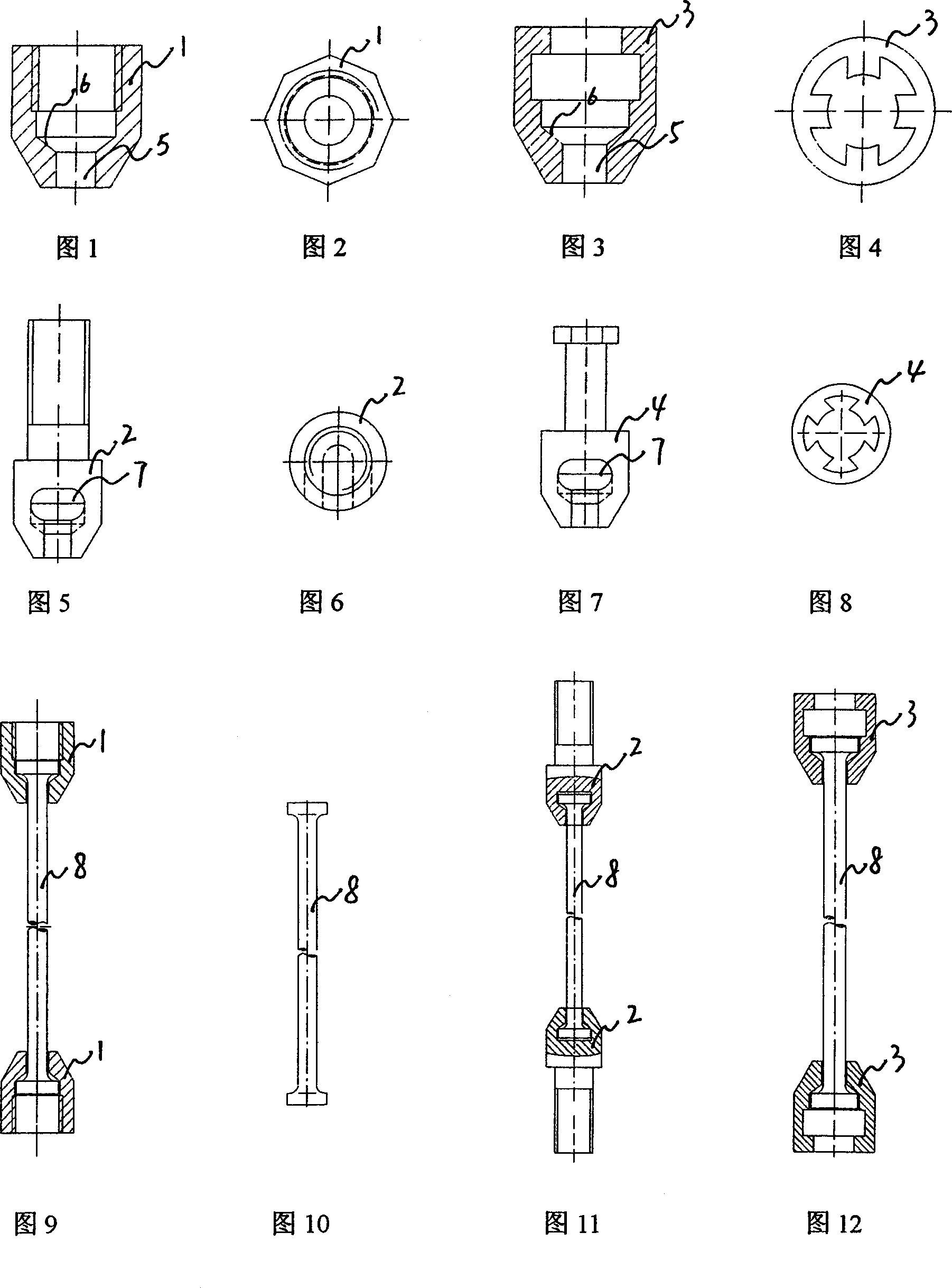
[0166] Embodiment 1: with reference to accompanying drawing 1~8. The prestressed pipe pile reinforced fasteners are made of cast steel, cast iron, forgings, steel, nylon and other materials and are formed into internal thread structures 1 and 2, see attached drawing 1; or in external threaded structure 2, see attached drawings 5 ​​and 6 ; or an internal clamping structure 3, see accompanying drawings 3 and 4; or an external clamping structure 4, see accompanying drawings 7 and 8; internal thread structure 1, external thread structure 2, internal clamping structure 3, external clamping The bottom center of the fastener cavity of the structure 4 is provided with a reinforcing bar hole 5, and the periphery of one end of the reinforcing bar hole is a reinforcing bar header card platform 6, and the header 7 of the reinforcing bar is clamped on the card platform. The shape of the strong-pull fastener with the internal card structure or the strong-pull fastener with the external card...

Embodiment 2

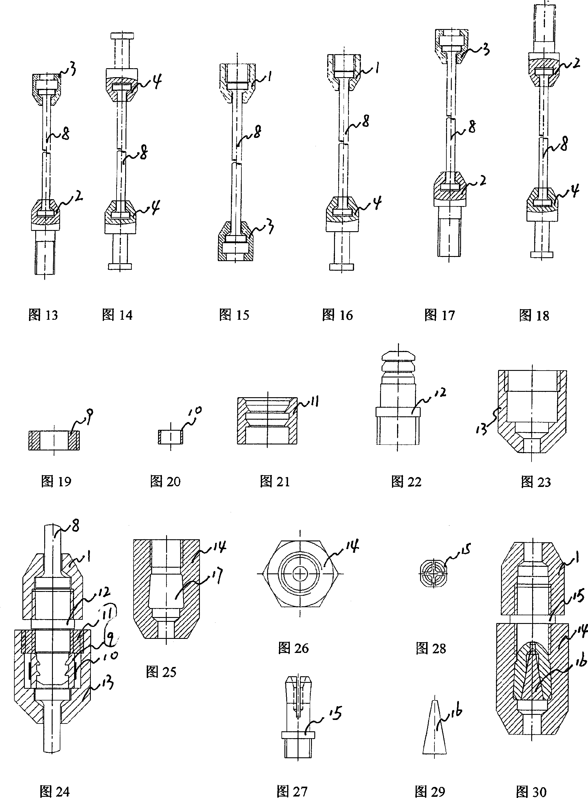
[0167] Embodiment 2: with reference to accompanying drawing 9 and 10. On the basis of Example 1, the prestressed pipe pile reinforced reinforcement fastener is composed of two fasteners 1 with internal thread structure and steel bars (steel rods) 8 .

Embodiment 3

[0168] Embodiment 3: with reference to accompanying drawing 11. On the basis of Embodiment 1, the prestressed pipe pile steel bar strong tension fastener is composed of two fasteners 2 with external thread structure and steel bars (steel rods) 8 .


PUM


Abstract

The present invention relates to one kind of powerful buckle for prefabricated unit, prefabricated unit with the buckle and it forming process. The powerful buckle has screw thread connecting or bayonet jointing structure with steel bar hole in the center and upset steel bar head clamping stage around the steel bar hole. The prefabricated pre-stressed unit has reinforcing rib skeleton comprising longitudinal ribs and ring ribs and the each end of its longitudinal ribs are bayonet jointed to the upset steel bar head clamping stage. After the powerful buckle has the end fixed onto the fixing board and expanding board and set inside formwork, and concrete is deposited and the expanding board is drawn to set pressure, to form centrifugal pile and obtain prefabricated pre-stressed unit.

Description

Technical field: [0001] The invention relates to a prefabricated strong fastener, a concrete prefabricated part composed of a prefabricated fastener, a butt joint structure between a prefabricated part and a prefabricated part, a docking method and a forming method of a prefabricated part, belonging to a prefabricated strong fastener and a prefabricated field of parts manufacturing. Background technique: [0002] Authorized announcement number CN2495685Y, name "Prestressed Concrete Pipe Pile Quick Connect", the joint includes two end plates and connecting pins fixedly connected to the upper and pile connection ends respectively, and threaded holes are opened in the end plates of the upper pile , one end of the connecting pin is threaded and can be matched with the threaded hole of the upper pile end plate, the other end is square, and there are teeth on both sides, a joint box is buried under the end plate of the lower pile, and the two joint boxes of the joint box A pressu...

Claims


Application Information

Patent Timeline
Patent Type & Authority Patents(China)
IPC IPC(8): E02D5/52E02D5/58E04B1/41
Inventor 周兆弟
Owner 周兆弟
Learn More