LCD micromotion exposure and development device

A technology of micro-motion and micro-motion stage, which is applied in the field of digital imaging, can solve the problems of low LCOS yield rate, difficulty in industrialization, and insufficient stability of technology, so as to ensure high stability and repeatability, reduce complexity and Price, high color vibrancy effect

Inactive Publication Date: 2007-11-07
SHANGHAI JIAOTONG UNIV
View PDF2 Cites 0 Cited by
  • Summary
  • Abstract
  • Description
  • Claims
  • Application Information

AI Technical Summary

Problems solved by technology

[0002] At present, most of the imaging systems that can output high-quality images come from companies such as Fuji, Kodak, and Noris. They use laser scanning exposure or low-light valve exposure methods, coupled with corresponding processing equipment, the price is expensive, and each unit is the lowest. It also needs to reach 700,000 yuan, which makes it difficult for most digital color expansion shops to accept
It can be seen that foreign technologies mainly have the following deficiencies: (1) The structure and technology of foreign imaging systems are complex and difficult to realize; (2) The cost is high and the utilization rate of equipment is low, making it difficult for consumers to accept; (3) Some key components used in the technology At present, it is still completely dependent on foreign supplies, and it is difficult to achieve industrialization, which seriously restricts the start and formation of my country's digital imaging industry
[0003] At present, there are very few digital imaging systems developed in China, and most of them use LCD technology. Due to the limitations of the low resolution and low aperture ratio of LCDs, it is far from meeting people's requirements for image quality when outputting larger-sized images, that is, The image resolution is extremely low; a small number of digital imaging systems use LCOS (liquid crystal on silicon) technology. Due to the low yield rate of LCOS and the technology is not stable enough, it cannot be used in practical applications at all.
[0004] At present, most LCD-based imaging systems use halogen lamps or xenon lamps as lighting sources, the output image color is less vivid, and it is difficult to control the color balance.
In addition, the available resolution of the current LCD is low, and the current domestic LCD-based imaging technology has no additional technical breakthroughs, resulting in only small-sized images being processed, and when the output image size is large, there will be a dark grid effect; based on The digital imaging system of LCOS cannot achieve practical application at all

Method used


Image

  • LCD micromotion exposure and development device
  • LCD micromotion exposure and development device
  • LCD micromotion exposure and development device

Examples


Embodiment Construction

[0020] The technical solution of the present invention will be further described below in conjunction with the accompanying drawings.

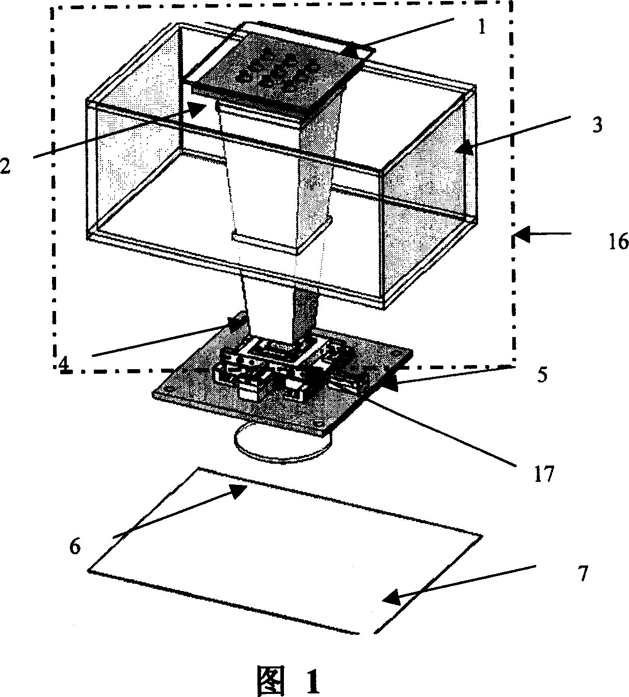
[0021] FIG. 1 is a schematic diagram of the structural composition of an embodiment of the micro-movement exposure device of the present invention. Within the scope of the dotted line in the figure is the multi-light source LED lighting system 16 of the present invention, which is composed of LED substrate 1, collimation frame 2, light mixing tube 4, and frosted glass 17 arranged on the same optical axis in sequence, and is fixed on the LED substrate 1. A group of red, green and blue three-color light-emitting diodes, a group of collimating mirrors are fixed on the collimation frame 2, and the outer surface of the light mixing tube 3 is embedded in the outer surface of the light mixing tube 4, which is used to fix the light mixing tube 3 and ensure the above part of the coaxial relationship. A collimation frame 2 is set close to the bottom of...


PUM


Abstract

It is a LCD micro exposal image-developing device used in LCD digit image-developing system. It adopts a group of emitting diodes fixed on the LED base plate of red, green and blue color. One group of calibration lens in the rack forms the emitting unit, which together with the light mixture cylinder and rough glass form the emitting system. The emitting system, LCD vibration bench, focus-adjusting project head and printing paper total axis form the whole LCD micro exposal image-developing device. And the LCD micro bench comprises micro bench base plate, LCD chip, LCD rack, micro bench limit block, piezoelectricity ceramics, piezoelectricity limit block and spring pad.

Description

technical field [0001] The invention provides a micro-moving exposure and developing device for LCD (liquid crystal) image technology, which is used to improve the lower image quality caused by the low aperture ratio and low available resolution of the LCD. It belongs to the technical field of digital imaging. Background technique [0002] At present, most of the imaging systems that can output high-quality images come from companies such as Fuji, Kodak, and Noris. They use laser scanning exposure or low-light valve exposure methods, coupled with corresponding processing equipment, the price is expensive, and each unit is the lowest. It also needs to reach 700,000 yuan, which makes it difficult for most digital color expansion shops to accept. It can be seen that foreign technologies mainly have the following deficiencies: (1) The structure and technology of foreign imaging systems are complex and difficult to realize; (2) The cost is high and the utilization rate of equipm...

Claims


Application Information

Patent Timeline
Patent Type & Authority Patents(China)
IPC IPC(8): G03B27/32
Inventor 孙文军王宇兴窦晓鸣赵海鹰罗培青
Owner SHANGHAI JIAOTONG UNIV
Why Eureka
Try Eureka