X-ray photography apparatus

a technology of x-ray and photography equipment, which is applied in the direction of radiation diagnostic diaphragms, patient positioning for diagnostics, applications, etc., can solve the problems of large burden on the patient, inability to take x-ray images in image diagnosis, and shortening the time of tooth taking

Active Publication Date: 2021-02-02
MORITA MFG CO LTD
View PDF36 Cites 0 Cited by
  • Summary
  • Abstract
  • Description
  • Claims
  • Application Information

AI Technical Summary

Benefits of technology

The patent is about a technology that can capture good quality tomographic images of teeth using X-rays. The X-rays are directed at the target tooth at a right angle, ensuring accurate and minimal distortion. The technology also allows for easy adjustment of the X-ray irradiation direction without burdening the test subject. Additionally, the patent explains how CT photography can be performed with the upper or lower jaw, making it convenient for dental procedures. The technical effects include the ability to capture accurate tomographic images of teeth and provide a more precise understanding of dental health.

Problems solved by technology

However, it is necessary to dispose in advance the X-ray detection means in the oral cavity of the patient, and thus a large burden is placed on the patient.
In the case that part of the row of teeth or the gums is irradiated with the X-ray such that the X-ray is not orthogonal to the tooth axis, there is a risk that an X-ray image becomes such an image that the tooth is obliquely looked down from above or that the tooth is obliquely looked up from below, and possibly the image of the tooth is taken shorter (or longer) than in reality.
The X-ray image is not desirable in an image diagnosis.
Therefore, the X-ray irradiation angle is undesirable with respect to the interest tooth, and the tomographic image equivalent to the X-ray image obtained by the intraoral radiography is hardly acquired.

Method used


Image

  • X-ray photography apparatus
  • X-ray photography apparatus
  • X-ray photography apparatus

Examples


Embodiment Construction

[0073]Hereinafter, preferred embodiments of the present invention will be described with reference to the accompanying drawings. In the drawings, for the sake of convenience, occasionally, the size or the number of pieces of each component is indicated while magnified or simplified as occasion demands.

[0074]1. Preferred Embodiment

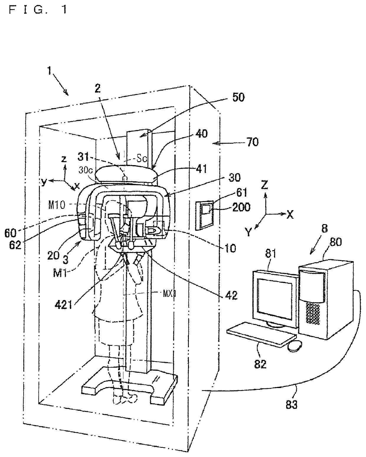
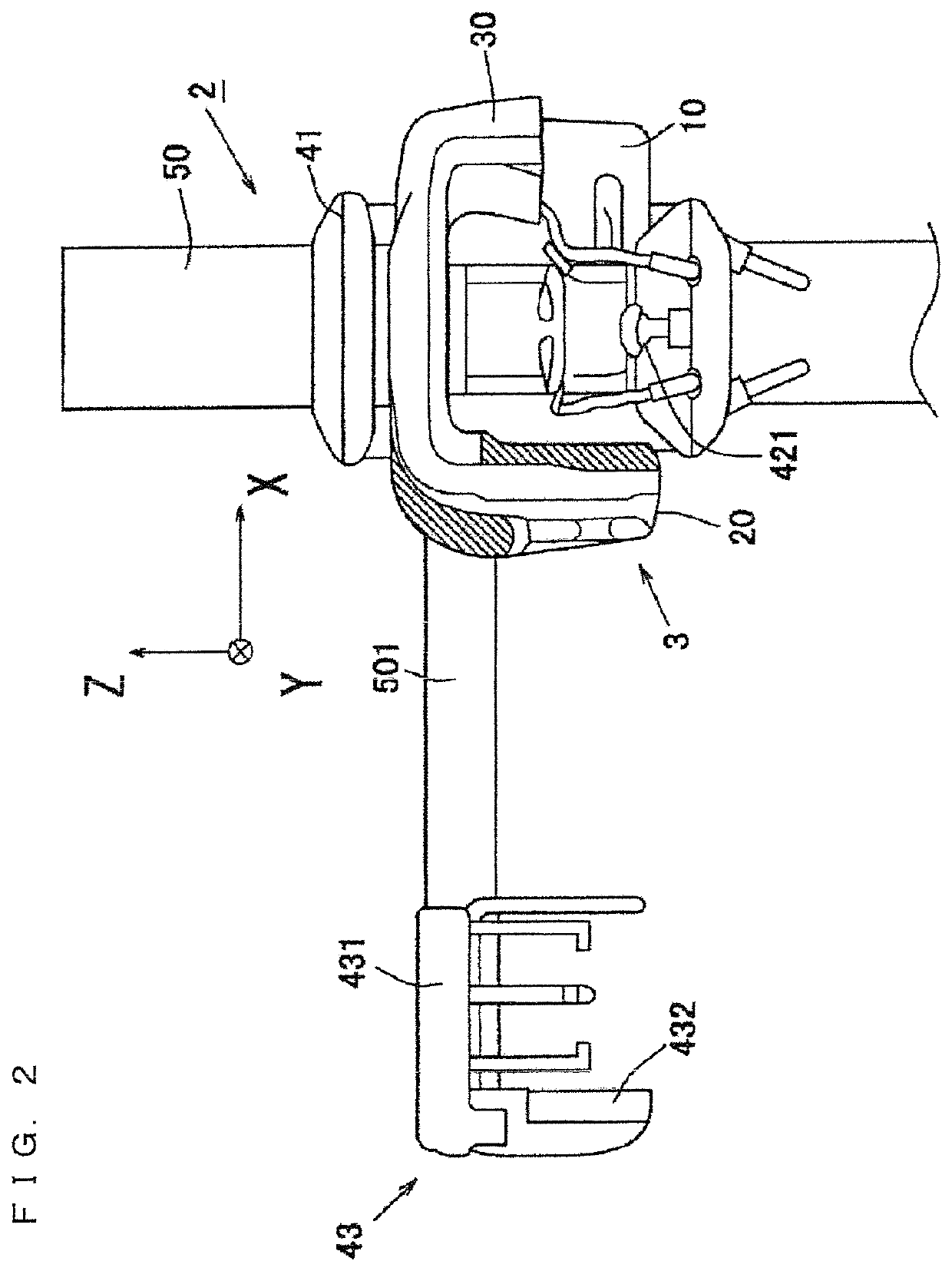
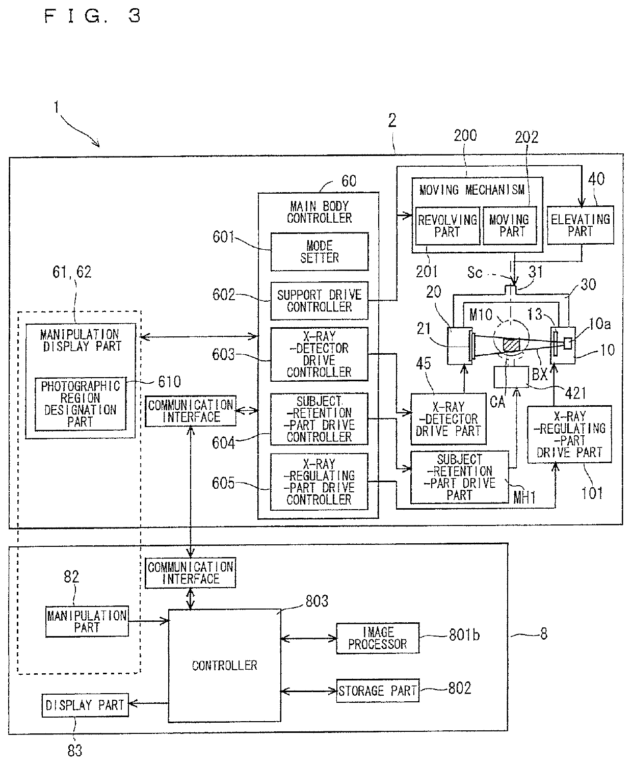
[0075]FIG. 1 is a schematic perspective view of an X-ray photography apparatus 1 according to a preferred embodiment of the present invention. FIG. 2 is a partial front view of the X-ray photography apparatus 1 on which a cephalostat 43 is mounted. FIG. 3 is a block diagram of the configuration of the X-ray photography apparatus 1.

[0076]The X-ray photography apparatus 1 is substantially comprised of manipulation display parts 61 and 62, a main body 2, and an image processing device 8. The manipulation display parts 61 and 62 act as display element while setting a photographic region CA. The main body 2 collects X-ray projection data (frame data) by performi...


PUM


Abstract

An X-ray photography apparatus including: a turning arm that supports an X-ray generator and an X-ray detector which are opposed to each other so that the head of a patient can be interposed therebetween, and a moving mechanism that includes a turning part and a moving part. The turning part turns the turning arm about a turning axis with respect to the head. The moving part moves the turning arm relative to the head in a direction perpendicular to the turning axis. The X-ray photography apparatus also includes: an image processor that generates an X-ray image, a photographic region designation part that designates part of a row of teeth along a dental arch as a pseudo intraoral radiography region, and an X-ray forming mechanism that changes the irradiation direction in which the head is irradiated with an X-ray relative to the axial direction of the body axis of the patient.

Description

BACKGROUND OF THE INVENTION[0001]1. Field of the Invention[0002]The present invention relates to an X-ray photography apparatus.[0003]2. Description of the Background Art[0004]Conventionally what is called intraoral radiography (dental radiography), in which an X-ray detection means (such as an X-ray film and an X-ray sensor panel) is set in the oral cavity of a patient to photograph part of a row of teeth or gums, is performed in X-ray photography of the dental field. Because only a local region is irradiated with an X-ray in the intraoral radiography, advantageously the photographing is simply performed and X-ray exposure is reduced. However, it is necessary to dispose in advance the X-ray detection means in the oral cavity of the patient, and thus a large burden is placed on the patient.[0005]Therefore, Japanese Patent Application Laid-Open No. 2007-136163 has made a proposal that panoramic photography is performed using a panoramic image photographing device and a tomographic im...

Claims


Application Information

Patent Timeline
Patent Type & Authority Patents(United States)
IPC IPC(8): A61B6/14A61B6/03A61B6/06A61B6/00A61B6/04
CPCA61B6/145A61B6/035A61B6/06A61B6/14A61B6/4476A61B6/469A61B6/5223A61B6/0478A61B6/0487A61B6/42A61B6/08A61B6/587A61B6/4452A61B6/51A61B6/512
Inventor YOSHIKAWA, HIDEKIHONJO, MAKOTO
Owner MORITA MFG CO LTD
Why Eureka
Try Eureka