
High efficiency, error minimizing coding strategy method and apparatus

a coding strategy and error-minimizing technology, applied in the field of coding data, can solve the problems of large discrepancies, limited number of bits that may be used to define code words, and errors in detection, transmission or reading of bit patterns, etc., and achieve the effect of minimizing errors, high efficiency, and minimizing coding strategies

Inactive Publication Date: 2012-12-25
SEAGATE TECH LLC
View PDF14 Cites 0 Cited by
  • Summary
  • Abstract
  • Description
  • Claims
  • Application Information

AI Technical Summary

Benefits of technology

[0015]In accordance with the present invention, a high efficiency, error minimizing coding strategy is provided. The present invention may be used in connection with any system that is susceptible to at least one dominant error in the transmission of data, and that can tolerate at least some deviation between a user value as recorded or transmitted and a user value as read or received. The coding strategy of the present invention allows data to be encoded such that errors are minimized, while maximizing the efficiency of the system.
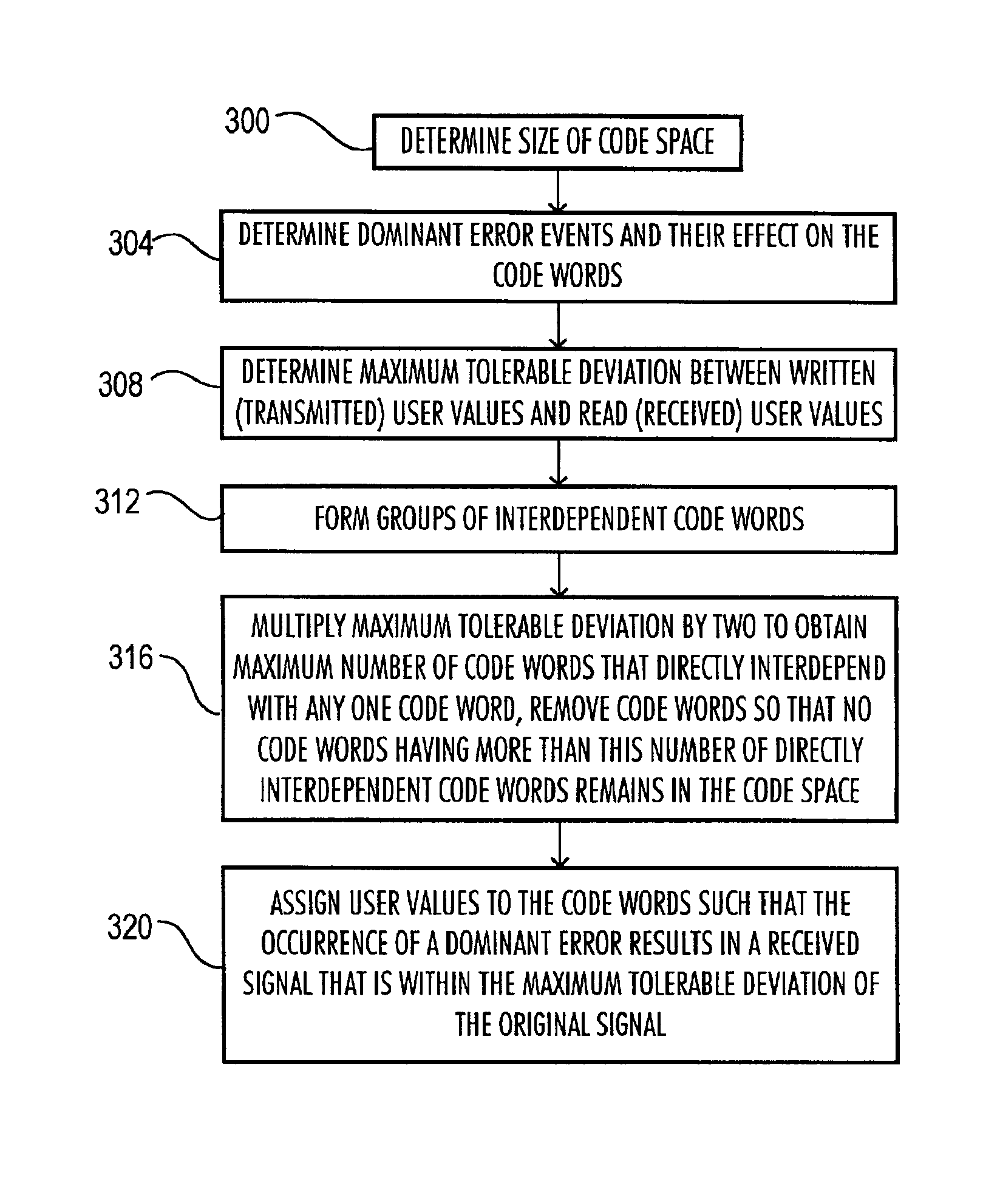
[0021]Based on the foregoing summary, a number of salient features of the present invention are readily discerned. A method for providing a high efficiency, error minimizing code is provided. The method enables a system having a dominant error or errors and that can tolerate at least some deviation between user values or data as stored or transmitted and user values or data as read or received to operate with high efficiency. Furthermore, the method of the present invention allows the maximum deviation between user values or data as stored or transmitted and user values as read or received due to a dominant error to be constrained to a chosen deviation amount. In addition, the present invention provides an apparatus in which errors in the transmission or reading of user values or data results in user values that are within a defined maximum tolerable deviation. The apparatus achieves this without requiring the use of redundant data.

Problems solved by technology

In most such digital communication systems, the number of bits that may be used to define code words is limited.
In many digital systems, errors in the detection, transmission or reading of bit patterns may occur.
In a typical coding scheme, a code word that is read incorrectly due to the occurrence of a dominant error can result in a very large discrepancy.
However, such “run length limited” codes reduce the efficiency of the code space by eliminating what would otherwise be valid code words.
However, each bit of a code word dedicated to parity checking or to error correction reduces the efficiency of the coding scheme.
In an actual system, however, it is difficult to write non-perturbed circular tracks 136 to the data storage disk 108.
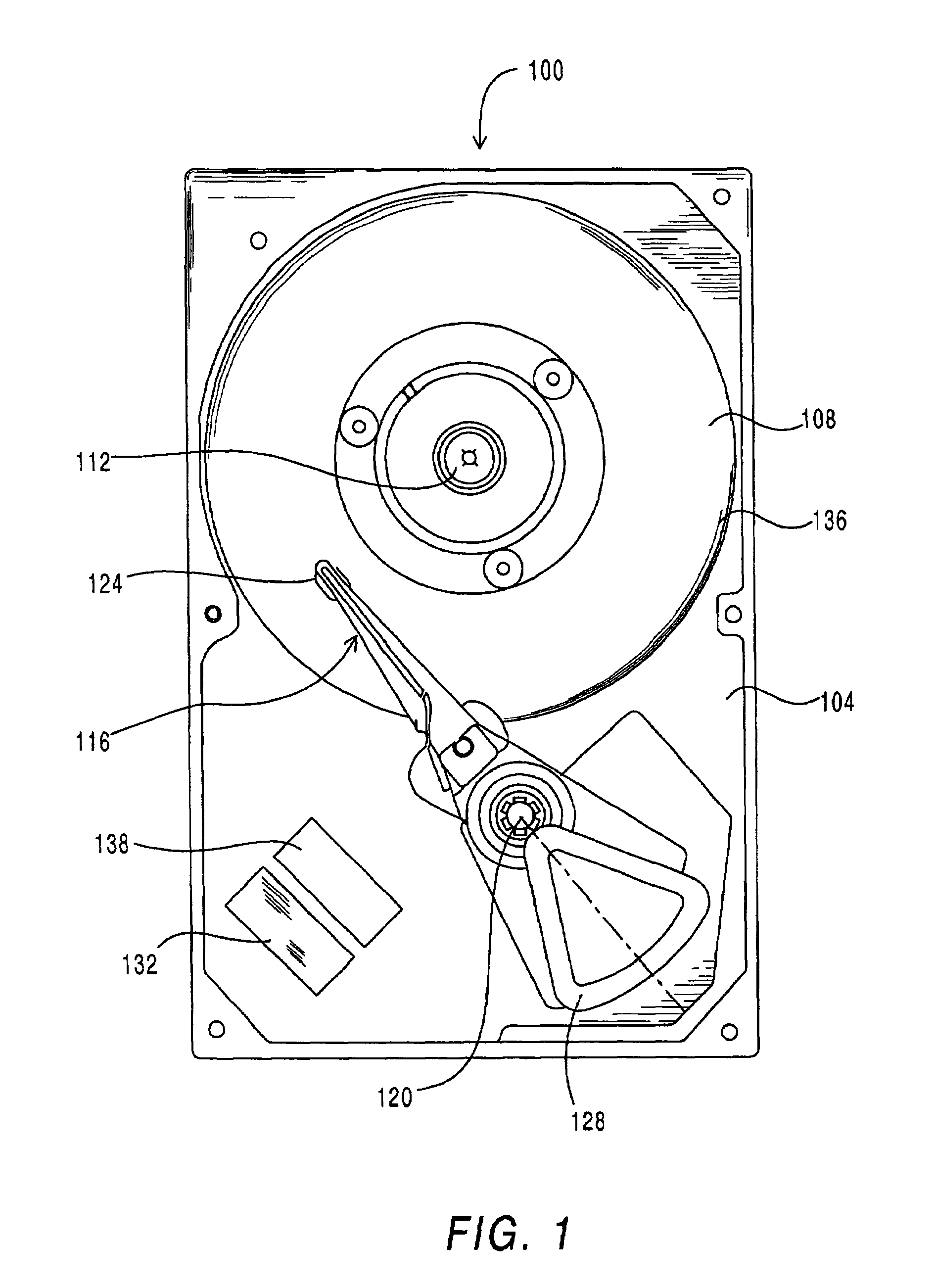
That is, problems such as vibration, bearing defects, inaccuracies in the servo track writer used to write the tracks 136 and disk clamp slippage can result in tracks 136 that are written differently from the ideal non-perturbed circular track shape.
However, conventional disk drive systems utilizing embedded run-out correction typically discard embedded runout correction values that are not correctly detected by a detector included as part of the channel 138.
Therefore, such conventional methods result in inefficiencies and / or the loss of useful data.
However, breaks in an audible signal due to such errors are annoying and can make a conversation difficult or impossible to follow.
Furthermore, typical communication channels used for transmitting voice data are susceptible to dominant errors.
In addition, errors that are not detected result in values that may be very different from the intended value.
Furthermore, errors that are detected but are not corrected may result in a code word being discarded, with no benefit being derived from the transmission of the discarded data.

Method used


Image

  • High efficiency, error minimizing coding strategy method and apparatus
  • High efficiency, error minimizing coding strategy method and apparatus
  • High efficiency, error minimizing coding strategy method and apparatus

Examples


Embodiment Construction

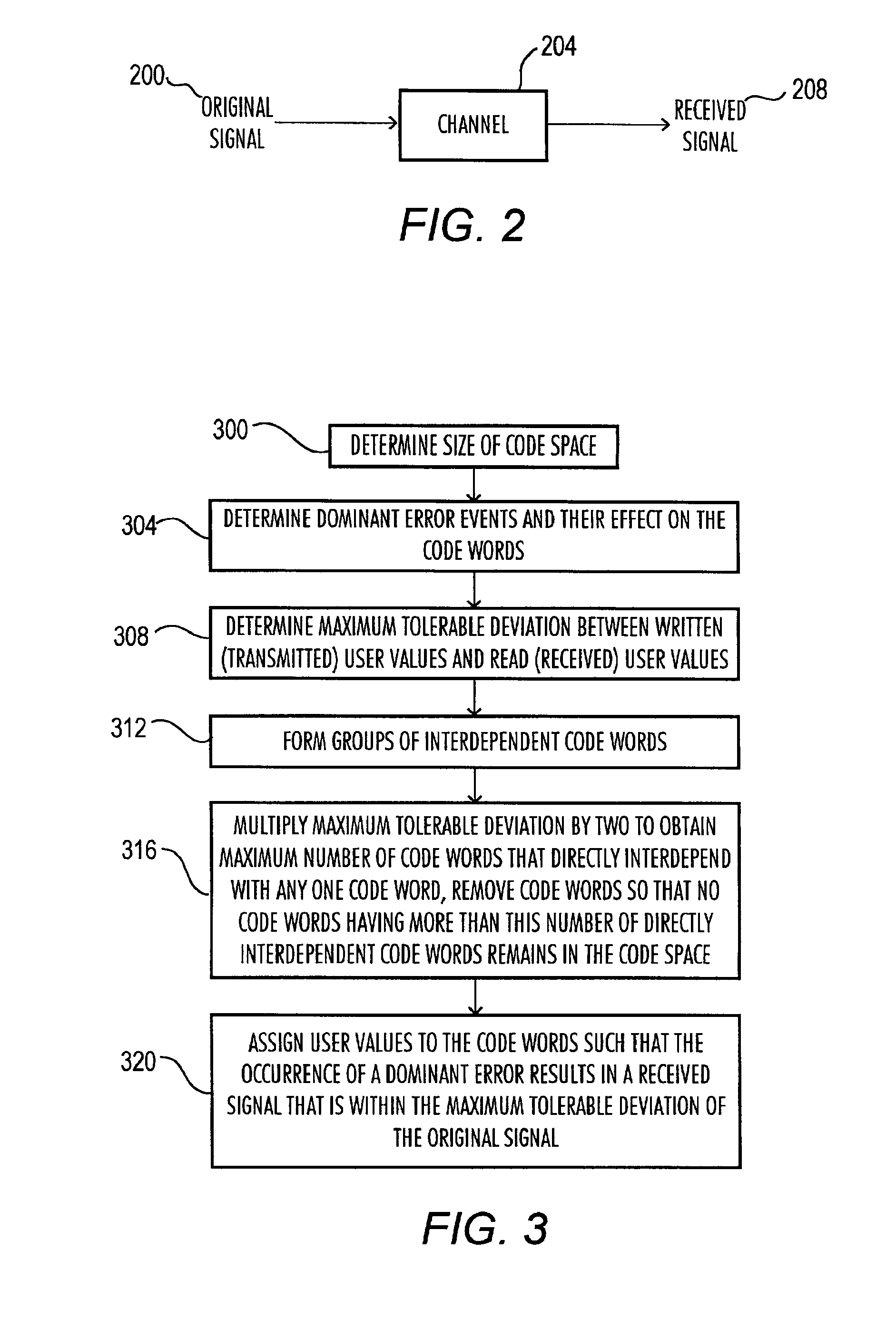
[0032]With reference now to FIG. 2, the relationship between an original signal 200, a communication channel 204 and a received signal 208 is illustrated. In general, the original signal 200 is subject to alteration by the communication channel 204 to result in a received signal 208 that is not identical to the original signal 200. As will be appreciated by those of ordinary skill in the art, the original signal 200 may be a signal read from storage, or a signal provided for transmission. As will further be appreciated by those of ordinary skill in the art, the communication channel 204 may comprise any apparatus for conveying information. Examples of communication channels 204 include voice data transmission systems, such as the plain old telephony system, a wireless communication channel for transmitting voice or data, a computer network, or a read element in combination with a detector, such as the transducer head 124 of a disk drive 100 in combination with a detector included as...


PUM


Abstract

A method for creating a high efficiency, error minimizing code is provided. In addition, an apparatus having a high efficiency, error minimizing code is provided. In particular, the present invention provides a high efficiency, error minimizing code for use in connection with systems having a communication channel in which identifiable dominant errors occur, and that is used to transmit data that may be usefully applied in the system even though the received signal is not exactly equal to the original signal. Furthermore, the present invention provides a code that may be used to constrain the effects of dominant errors in a communication channel.

Description

RELATED PATENT DOCUMENTS[0001]More than one reissue application has been filed for the reissue of U.S. Pat. No. 7,404,131. The reissue applications are application Ser. No. 13 / 330,177 filed Dec. 19, 2011 (the present application), which is a divisional reissue of U.S. Pat. No. 7,404,131), and Ser. No. 12 / 840,974 filed Jul. 21, 2010, which is a reissue application of U.S. Pat. No. 7,404,131.FIELD OF THE INVENTION[0002]The present invention relates to coding data. In particular, the present invention relates to a method and apparatus for encoding data that is highly efficient, and that minimizes the effect of errors.BACKGROUND OF THE INVENTION[0003]Coding schemes are regularly used in connection with the transmission of data. For example, in digital communication systems, data is typically transmitted as a series of code words. In general, each code word is assigned a unique pattern of bits, with each bit consisting of either a zero or a one. In most such digital communication systems...

Claims


Application Information

Patent Timeline
Patent Type & Authority Patents(United States)
IPC IPC(8): H03M13/00G11C29/00
CPCH04L1/0045
Inventor MCCARTHY, STEVESEABURY, JOHN
Owner SEAGATE TECH LLC
Learn More