
Method and apparatus for providing translucent images on a computer display

a computer display and translucent technology, applied in the field of computer systems, can solve the problems of occupying valuable screen space, seriously degrading the keyboard, if included in the pen system,

Inactive Publication Date: 2010-11-09
APPLE INC
View PDF45 Cites 127 Cited by
  • Summary
  • Abstract
  • Description
  • Claims
  • Application Information

AI Technical Summary

Benefits of technology

[0020]An advantage of the present invention is that a translucent overlay can be provided which permits a user to input data into an active application program without obscuring the user's view of the program's display window. The overlay image of the present invention is therefore well suited for computer systems having limited display areas, including for example pen computer systems.
[0021]Another advantage of the overlay image of the present invention is that it works with both pen-aware and non-pen-aware application programs. Therefore, the overlay image of the present invention can be used with the many thousands of application programs which are not designed to be used in pen computer systems.
[0022]These and other advantages of the present invention will become apparent upon reading the following detailed descriptions and studying the various figures of the drawings.

Problems solved by technology

In addition, a primary feature of many pen computer systems is their portability, which a keyboard, if included with the pen system, would seriously degrade.
A problem with all such input approaches is that they occupy valuable screen space, which is often very limited on pen computer systems.

Method used


Image

  • Method and apparatus for providing translucent images on a computer display
  • Method and apparatus for providing translucent images on a computer display
  • Method and apparatus for providing translucent images on a computer display

Examples


Embodiment Construction

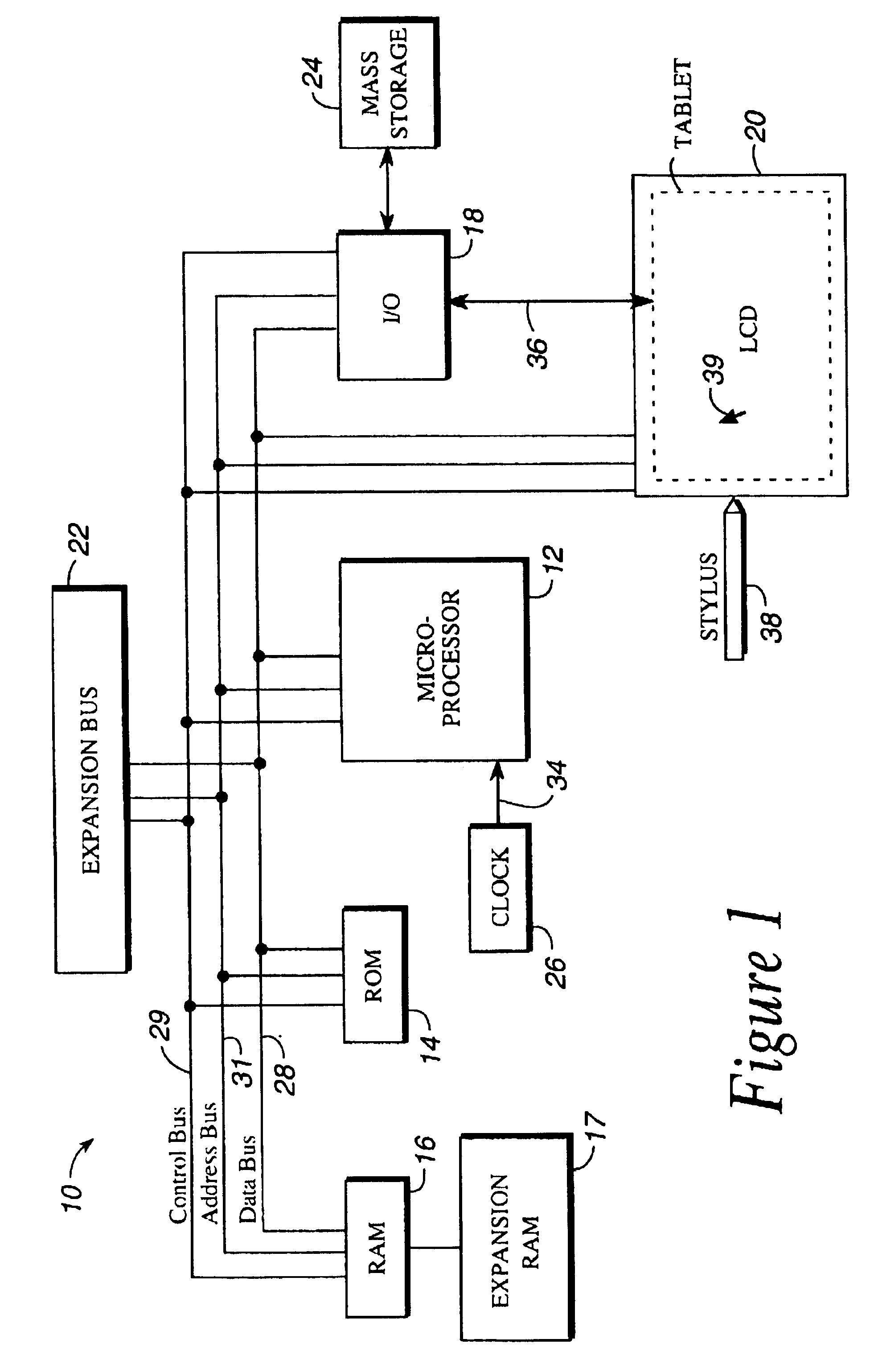
[0062]As shown in FIG. 1, a computer system 10 in accordance with the present invention includes a central processing unit (CPU) 12, read only memory (ROM) 14, random access memory (RAM) 16, expansion RAM 17, input / output (I / O) circuitry 18, display assembly 20, and expansion bus 22. The computer system 10 may also optionally include a mass storage unit 24 such as a disk drive unit or nonvolatile memory such as flash memory and a real-time clock 26.

[0063]The CPU 12 is preferably a commercially available, single chip microprocessor, and is preferably a complex instruction set computer (CISC) chip such as the 68040 microprocessor available from Motorola, Inc. CPU 12 is coupled to ROM 14 by a data bus 28, control bus 29, and address bus 31. ROM 14 contains the basic operating system for the computer system 10. CPU 12 is also connected to RAM 16 by busses 28, 29, and 31 to permit the use of RAM 16 as scratch pad memory. Expansion RAM 17 is optionally coupled to RAM 16 for use by CPU 12...


PUM


Abstract

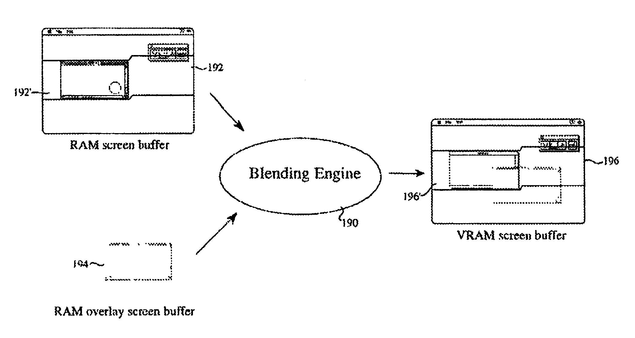
A method and apparatus is described for producing a translucent image over a base image created on the display screen of a computer system by a selected first application program, and conducting image operations either on the base image created by the selected application program with reference to the translucent image produced, or conducting image operations on the translucent image with reference to the base image of the first application program. The first application program runs on a central processing unit (CPU) of a computer system to produce a base image, and another application program referred to as the overlay program is run to produce the translucent image such that portions of the base image which are overlapped by the overlay image are at least partially visible through the translucent image. There is also a mechanism for blending the first video data and the second video data to produce a blended image on the screen assembly.

Description

CROSS-REFERENCE TO A RELATED APPLICATIONRELATED APPLICATIONS [0001]This application is a broadening reissue of U.S. Pat. No. 6,072,489, issued on Jun. 6, 2000. U.S. Pat. No. 6,072,489is a continuation-in-part of patent application Ser. No. 08 / 060,572, filed May 10, 1993 under the title “Method and Apparatus for Displaying an Overlay Image,” now U.S. Pat. No. 5,638,501 on behalf of Gough et al. and assigned to the same assignee as herein, the disclosure of which is hereby incorporated herein by reference in its entirety. Priority rights and claims of benefit based upon this earlier-filed patent application are claimed. More than one reissue application has been filed for the reissue of U.S. Pat. No. 6,072,489. The reissue applications are application Ser. Nos. 10 / 163,748 (the present application), and 12 / 437,500 a continuation reissue of U.S. Pat. No. 6,072,489. <?insert-end id="INS-S-00004" ?>BACKGROUND OF THE INVENTION[0002]This invention relates generally to computer systems...

Claims


Application Information

Patent Timeline
Patent Type & Authority Patents(United States)
IPC IPC(8): G06T15/00G06F3/0481G09G5/14G09G5/36G09G5/39G09G5/395
CPCG06F3/0481G06F2203/04804G09G3/3611G09G5/14G09G5/36G09G5/39G09G5/395G09G2340/10
Inventor GOUGH, MICHAEL L.MACDOUGALD, JOSEPH J.VENOLIA, GINA D.GILLEY, THOMAS S.ROBBINS, GREG M.HANSEN, JR., DANIEL J.OSWAL, ABHAY
Owner APPLE INC
Learn More