
Female incontinence prevention device

a technology for incontinence and prevention devices, applied in the field of incontinence prevention devices, can solve the problems of affecting the safety of patients, cumbersome use, and inconvenient use, and achieve the effects of preventing spraying, simple and inexpensive construction, and convenient us

Inactive Publication Date: 2007-05-15
CONSERT INC
View PDF9 Cites 6 Cited by
  • Summary
  • Abstract
  • Description
  • Claims
  • Application Information

AI Technical Summary

Benefits of technology

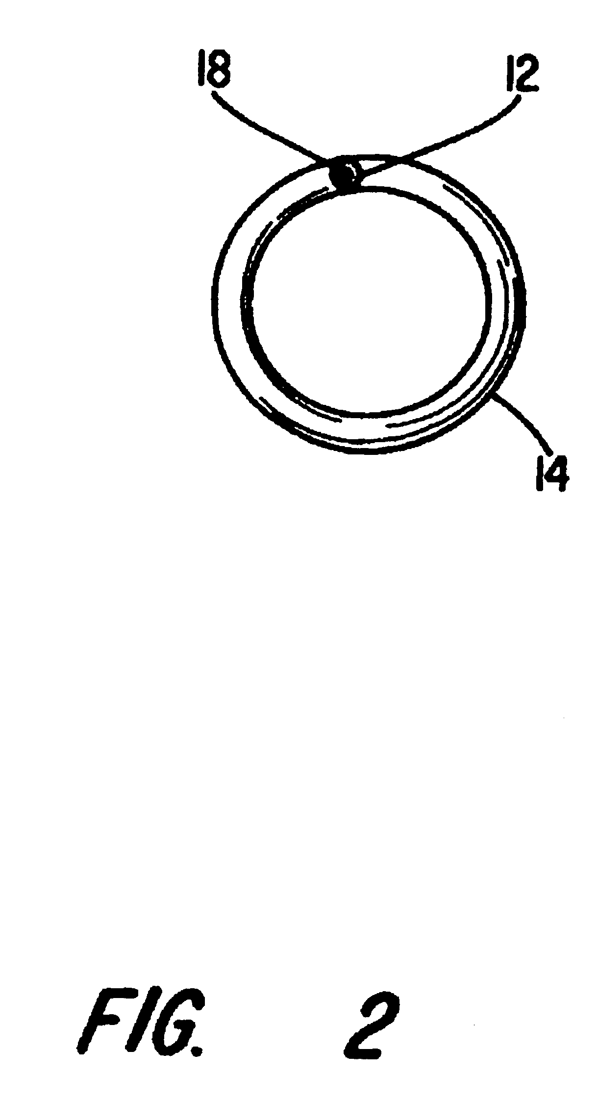
[0008]The present invention further provides an incontinence prevention device that is simple and inexpensive to construct and easy to use. The incontinence prevention device of the present invention includes a shaft and a retention structure. The retention structure is configured as a closed loop non-concentrically disposed about a longitudinal axis of the shaft. The retention structure's closed loop tends to maintain the incontinence prevention device within the bladder neck. The retention structure's non-concentrically orientation accounts for the bladder's asymmetry. The retention structure may further include a protuberance projecting from the retention structure. The protuberance may project from a midpoint of the closed loop. The shaft may further include a lumen configured to receive a stylet. The lumen is typically coextensive with the shaft and substantially coextensive with the retention structure. In addition, the lumen may be coextensive with the protuberance. The device may also include a hydrogel coating disposed on its outer surface. The shaft may include an orientation marking at its proximal end. The proximal end of the shaft may also have a beveled edge to prevent the spraying of urine during urination. A segment of the retention structure may additionally define a cavity to receive another portion of the retention structure to further reduce the diameter for insertion. For insertion, the retention structure is rendered substantially rectilinear. A stylet may be provided to insert into a lumen in the device to render the retention structure substantially rectilinear. Once rectilinear, the device is inserted into the urethra so that the retention structure is placed within the bladder. Once in the bladder, the retention structure is reformed into a loop. The retention structure is then positioned adjacent the neck of the bladder with the non-concentrically disposed retention structure in a predetermined orientation.

Problems solved by technology

Surgical correction is possible in some cases, but surgery is invasive, costly and dangerous.
Urethral incontinence prevention devices, such as for example catheters, plugs and other similar devices, in most cases offer a better solution but can be cumbersome to use, can be expelled during bowel movements, and are typically relatively expensive to manufacture.
Because the bladder is continuously emptied, the bladder's dome continuously rests on the tip of the catheter above the retention balloon causing compression, irritation and erosion of tissue as well as other tissue problems.
After removal, the old plug is not sterile and a new sterile plug must inserted into the urethra Plugs' retention structures are typically cumbersome to operate and traumatic to the tissue.
Thus, improper use can lead to irritation and infection from tissue traumatization.
Further, the retention devices on the plugs are typically fluid filled and therefore relatively complex to manufacture.
These devices may be expelled when a user tenses the abdomen, such as when a user bears down during a bowel movement, because of a phenomenon called bladder neck drop often associated with incontinent female patients.
The improperly positioned device no longer functions properly and the quasi-rectilinear bladder retention structure can no longer maintain the device at its proper location permitting the user to later expel the device.
The scattering of urine is inconvenient and unsanitary.

Method used


Image

  • Female incontinence prevention device
  • Female incontinence prevention device
  • Female incontinence prevention device

Examples


Embodiment Construction

[0015]The present invention is applicable to a variety of devices that are maintained in the urethra. The invention is described in the context of an incontinence device for a woman's urethra for exemplary purposes. The appended claims are not intended to be limited to any specific example or embodiment described in this specification. It will be understood by those skilled in the art that the present invention may be used in related medical applications including but not limited to incontinence prevention devices, obstruction relief devices, drainage devices; or other similar devices which require retention in a lumen. Further, in the drawings described below, the reference numerals are generally repeated where identical elements appear in more than one figure.

[0016]FIG. 1 illustrates an embodiment of an incontinence prevention device 10 in accordance with the present invention. Device 10 includes a shaft 12, a retention structure 14 and a proximal retention structure 15. Device 10...


PUM


Abstract

The disclosure provides an incontinence prevention device provided with a loop type retention structure. The retention structure is in the form of a closed loop attached to the distal end of a shaft. The shaft is configured to function as an incontinence prevention device. The retention structure projecting laterally from and configured non-concentrically along the longitudinal axis of the shaft retains the incontinence prevention device within the patient. The retention structure may additionally include a protuberance extending therefrom. There is further provided a method for using the urethral catheter.

Description

FIELD OF INVENTION[0001]The present invention relates generally to incontinence prevention devices, and more particularly to an incontinence prevention devices having a non-concentric retention structures.BACKGROUND OF INVENTION[0002]Many adults suffer urinary incontinence although urinary incontinence is more common in women than in men. The increased frequency in women is due primarily to the laxity of the bladder support structures resulting from pregnancy and aging. Surgical correction is possible in some cases, but surgery is invasive, costly and dangerous. Urethral incontinence prevention devices, such as for example catheters, plugs and other similar devices, in most cases offer a better solution but can be cumbersome to use, can be expelled during bowel movements, and are typically relatively expensive to manufacture.[0003]There are a wide variety of incontinence prevention devices available, including: catheters that have lumen for urine to flow through; valved catheters; p...

Claims


Application Information

Patent Timeline
IPC IPC(8): A61F5/48A61F2/00
CPCA61F2/0022Y10S128/25
Inventor TIHON, CLAUDE
Owner CONSERT INC
Learn More