Eureka AIR delivers breakthrough ideas for toughest innovation challenges, trusted by R&D personnel around the world.

Conveyor and conveyor belt cleaning sprocket

Inactive Publication Date: 2006-07-18
MONTGOMERY PRESTON D
View PDF31 Cites 4 Cited by
  • Summary
  • Abstract
  • Description
  • Claims
  • Application Information

AI Technical Summary

Benefits of technology

[0009]Preferably, the length of the one sprocket is substantially equal to the width of the belt, and the fluid conduit extends from the one end substantially to the other end of the body. This configuration allows the outlet passages and the apertures to be positioned in spaced relation lengthwise along the body, thus, ensuring that the entire width of the belt is subjected to the cleaning spray of fluid flowing out of the apertures.
[0017]It is another object of the invention to provide an endless conveyor which does not require disassembly to effect cleaning.

Problems solved by technology

Because of the many hinges and joints required to ensure flexibility such belts have a marked tendency to accumulate debris on their inside surface as well as other normally inaccessible places such as in the joints between the segments.

Method used


Image

  • Conveyor and conveyor belt cleaning sprocket
  • Conveyor and conveyor belt cleaning sprocket
  • Conveyor and conveyor belt cleaning sprocket

Examples


Embodiment Construction

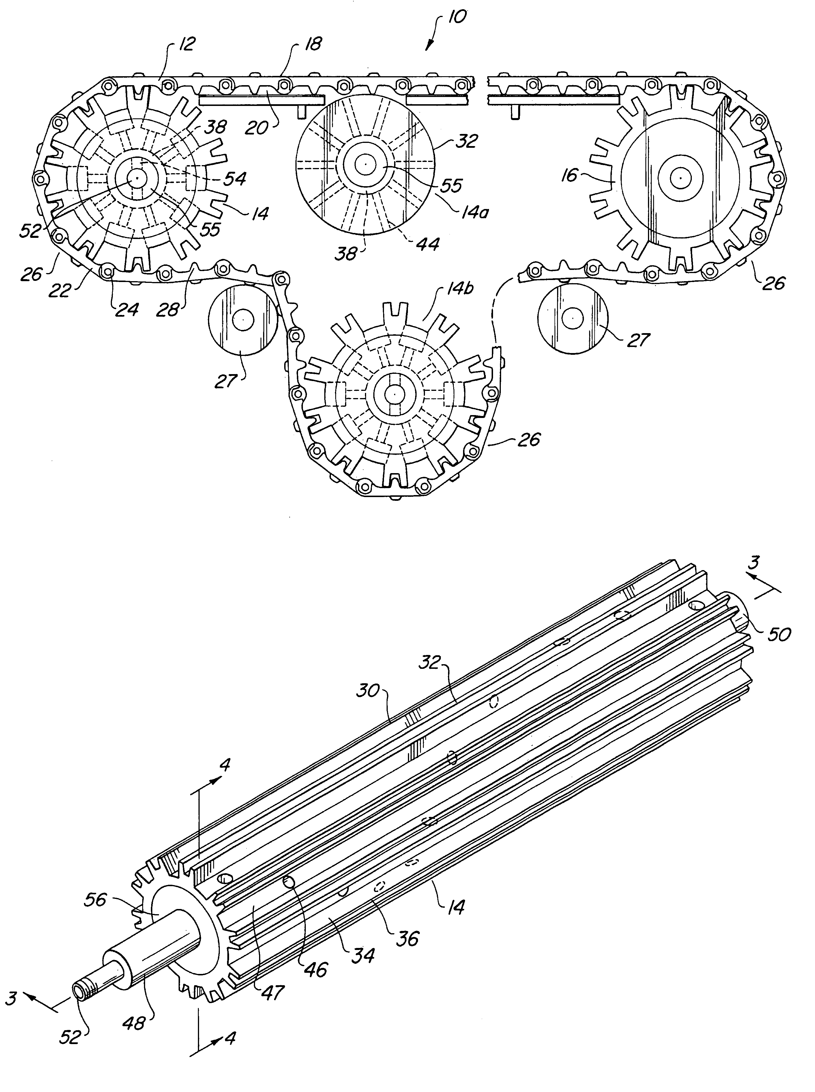
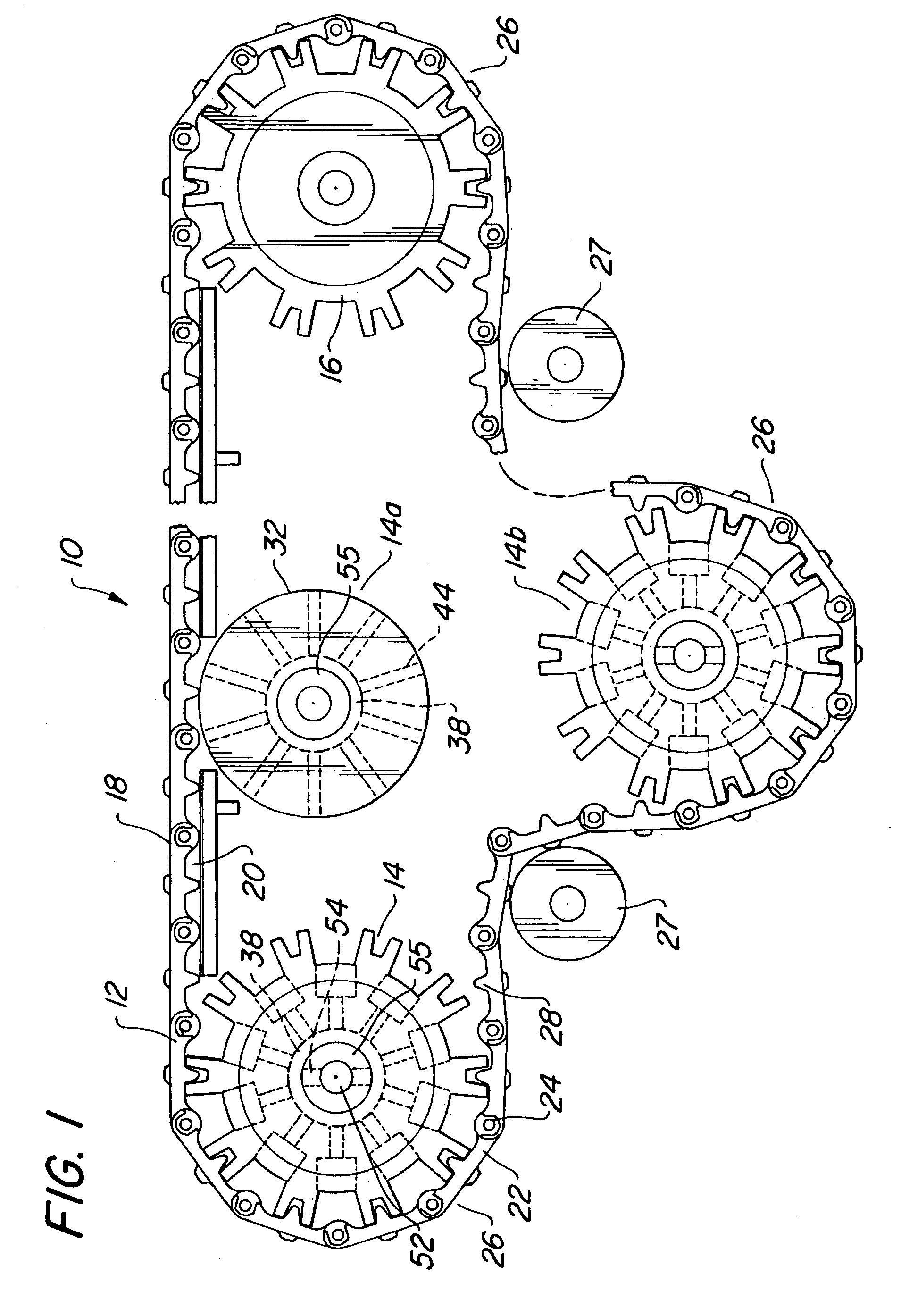
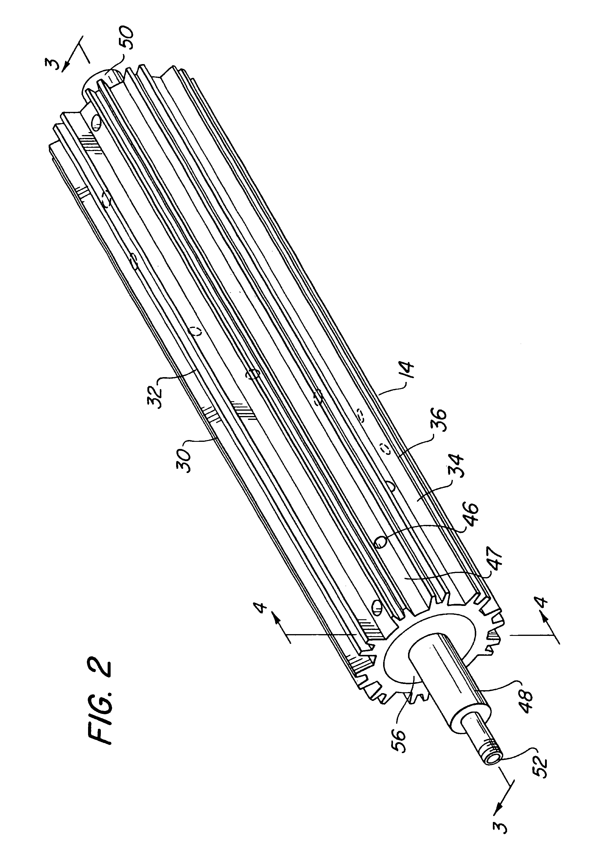
[0027]FIG. 1 shows an endless conveyor 10 according to the invention, the conveyor having an endless belt 12 suspended between two rotatably mounted sprockets 14 and 16. Belt 12 has an outwardly facing surface 18 on which the items to be transported by the belt are supported and an inwardly facing surface 20 opposite the surface 18 and engaging sprockets 14 and 16. Belt 12 is preferably made of a plurality of segments 22 arranged side by side and hingedly connected to one another by hinge pins 24 allowing segments 22 to pivot relative to one another when traversing around sprockets 14, 14b and 16 as shown at positions 26 in FIG. 1. Preferably, segments 22 have mating teeth 28 projecting from the inwardly facing surface 20 to engage teeth on sprockets 14, 14b and 16 described below. As noted above, sprocket 14 could be an idler sprocket, a driver sprocket, a support roller such as 14a in FIG. 1, positioned to engage inwardly facing surface 20 of belt 12 at intermediate points along i...


PUM


Abstract

A sprocket for an endless conveyor is disclosed having a plurality of fluid outlet passages arranged radially between the center of the sprocket and its outer circumferential surface. The outlet passages are positioned along the length of the sprocket in a helical path and are in fluid communication with an annular fluid conduit extending lengthwise along the center of the sprocket. A fluid inlet connected to the conduit supplies fluid under pressure to the conduit, the fluid spraying radially outwardly through the outlet passages to impinge on the inside surface of the endless conveyor and remove any accumulated debris. Nozzles are positioned within the outlet passages to control the fluid spray.

Description

RELATED APPLICATION[0001]This application is based on and claims the benefit of prior filed co-pending provisional patent Application No. 60 / 200,793, filed Apr. 28, 2000.FIELD OF THE INVENTION[0002]This invention relates to sprockets used with endless conveyors, and especially to sprockets which are adapted to clean the conveyor when in operation.BACKGROUND OF THE INVENTION[0003]Conveyors comprising sprocket driven endless belts are used in a wide spectrum of industrial applications to transport items being manufactured or processed from point to point. The items being transported may leak or ooze liquids of varying viscosity, or shed dust, dirt, particles or debris which can accumulate on the belt and foul the conveyor.[0004]This problem is especially acute in meat processing equipment where cuts of meat are transported on conveyors between processing stations and ooze blood, deposit viscous or congealed fat, cartilage, muscle, and other animal carcase liquids and debris onto the b...

Claims


Application Information

Patent Timeline
IPC IPC(8): B65G45/22
CPCB65G45/22
Inventor MONTGOMERY, PRESTON D.
Owner MONTGOMERY PRESTON D
Why Eureka
Eureka Blog
Learn More