
Motion compensation predicting encoding method and apparatus

a motion compensation and coding technology, applied in the field of image encoding systems, can solve the problems of low coding efficiency and achieve the effect of efficient quantization

Inactive Publication Date: 2002-09-24
MITSUBISHI ELECTRIC CORP
View PDF17 Cites 25 Cited by
  • Summary
  • Abstract
  • Description
  • Claims
  • Application Information

AI Technical Summary

Benefits of technology

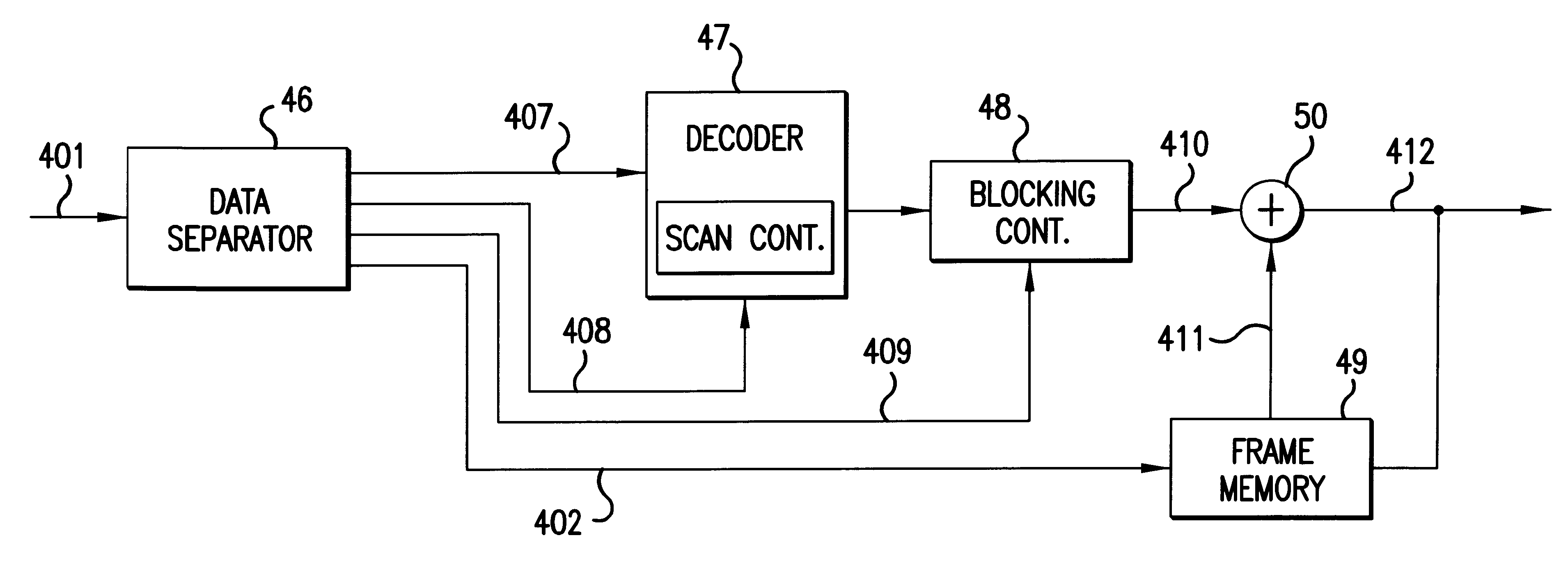
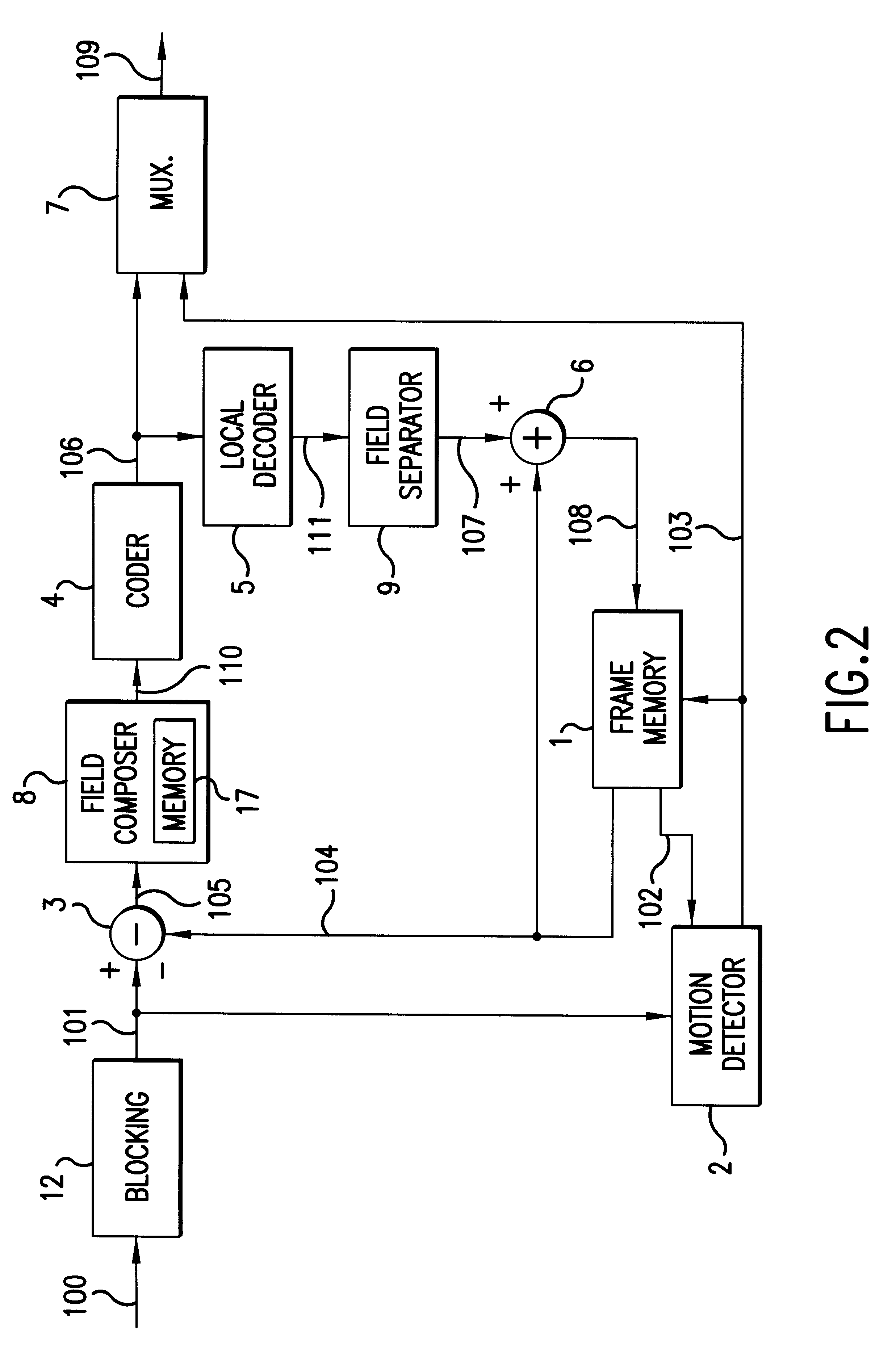
The coder for encoding output may include several components. First, the code may include a transformation means for performing an orthogonal transformation on the prediction error signal to produce a coefficient matrix. Second, the coder may include a quantizer for quantizing the coefficients from the coefficient matrix and a scanning controller for controlling what order the coefficients are scanned from the coefficient matrix and passed to the quantizer. This order is preferably controlled by the motion vectors. In particular, the motion vectors indicate whether there will be large horizontal components or large vertical components that are most efficiently quantized by altering the scanning order of the coefficient matrix. These elements may be used in conjunction with the above-described components.

Problems solved by technology

However, the temporal correlation between continuous different fields subjected to the interlaced scanning is not used, and, hence, the coding efficiency is low.

Method used


Image

  • Motion compensation predicting encoding method and apparatus
  • Motion compensation predicting encoding method and apparatus
  • Motion compensation predicting encoding method and apparatus

Examples


second embodiment

In this second embodiment, an input image signal 300 is input to the motion detector 32 and the memory 41. This input image signal 300 is already organized into blocks. In the motion detector 32, a determination is made in the adaptive composer 39 using the motion vector 302 whether the coding is carried out in a field composition mode or in a field independent mode. For example, when the motion vectors of both the fields are coincident with each other, both the fields are composed.

The adaptive composer 39 composes the field independent prediction error signal 304 into blocks on the basis of the motion vector 302, as shown in FIGS. 7A-7C. In FIGS. 7A-7C, ".largecircle." indicates a pixel of the odd field, and ".quadrature." indicates a pixel of the even field. Further, the shading indicates a difference in illuminance. FIG. 7A shows a block of the prediction error signal 304 in which field composition has been properly carried out, that is, by alternately arranging the pixels of the...

third embodiment

The third embodiment operates as follows. An input image signal 300, which is organized into blocks of even field pixels and blocks of odd field pixels, is fed to the first motion detector 43 and the memory 41. The input image signal 300 is stored in the memory 41. The input image signal 300 is also sent to the first motion detector 43. The previously received image signal 301 is read out of the memory 41 and sent to the first and second motion detectors 32 and 43. The image signal 301 is also sent to the subtracter 34. The first motion detector 43 calculates a motion vector 306 between the odd and even fields of the input image signal 300 and the image signal 301 in the same manner as described above for the previous embodiments. The motion vector 306 is then sent to the MUX 38, the adaptive composer 39, and the adaptive decomposer 40. The second motion detector 32 calculates a motion vector 302 indicating the motion between the odd field of image signal 301 and an odd field of a n...

fourth embodiment

The fourth embodiment operates as follows. In this embodiment, motion compensation is carried out from a frame input signal in which two fields are being composed (i.e., the frame input signal is compared with the frame image data stored in frame memory 33). Specifically, an input image signal 300 that has been obtained by an interlaced scanning is composed into one frame in the field composer 31. The field composing performed by field composer 31 is realized in the manner shown in FIGS. 4A-4C. That is, when the input image signals of the odd and even fields are as shown in FIGS. 4A and 4B, respectively, the lines of these two fields are alternately combined to obtain a field composition frame input signal 301 as shown in FIG. 4C. The obtained field composition frame input signal 301 is sent to the motion detector 32 and the subtracter 34.degree.

In the above discussion, the coder is described as performing the coding by DCT, which is kind of orthogonal transformation. It is, however...


PUM


Abstract

A motion compensation predicting coding apparatus includes a motion detector for comparing pixel data in an image signal with pixel data of the previous image signal to generate a motion vector. The motion vector is indicative of the displacement differences between the image signal and the previous image signal. The image signal may be organized into blocks of pixel data for a single field or for multiple fields when notion detection is performed on the image signal by the motion detector. A subtracter generates a prediction compensation error signal by subtracting the pixel data in the previous image signal from the pixel data of the image signal. A coder receives the prediction compensation error signal and generates an appropriate coded output. The apparatus may also include an adaptive blocking mechanism for receiving the prediction compensation error signal and organizing the data in the signal into blocks into one of several fashions as dictated by the motion vector.

Description

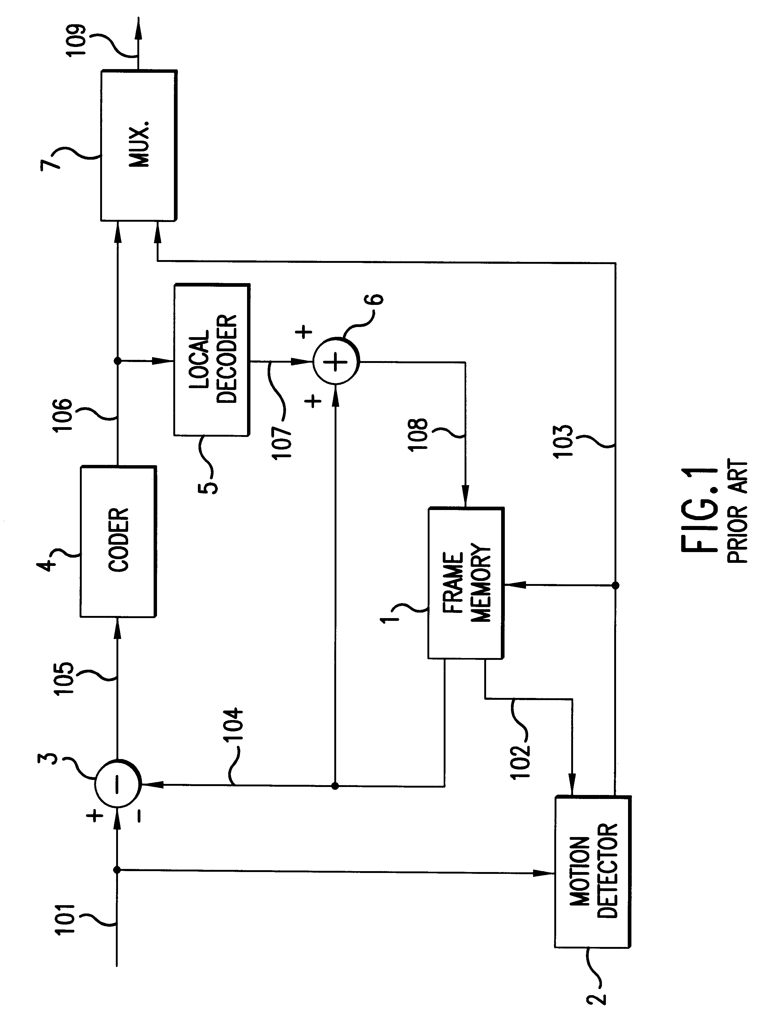
BACKGROUND OF THE INVENTIONi) Field of the InventionThe present invention relates generally to image encoding systems and, more particularly, to motion compensation predicting coding systems.ii) Description of the Prior ArtFIG. 1 shows a conventional motion compensation predicting coding apparatus, as disclosed in "A Study on HDTV Signal Coding with Motion Adaptive Noise Reduction" by S. Nogaki, M. Ohta and T. Omachi, The Third HDTV International Workshop Preliminary Report, Vol. 3, 1989. The conventional motion compensation predicting coding apparatus encodes a digital image signal 101 to produce a coded signal 106 that is sent over a transmission line 109. The conventional motion compensation predicting coding apparatus includes a frame memory 1, a motion detector 2, a subtracter 3, a coder 4, a local decoder 5, an adder 6 and a multiplexer (MUX) 7. At a destination, the coded data is decoded to reproduce the original image signal 101. The destination has an architecture similar t...

Claims


Application Information

Patent Timeline
Patent Type & Authority Patents(United States)
IPC IPC(8): H04N7/26
CPCH04N19/105H04N19/112H04N19/137
Inventor MURAKAMI, TOKUMICHIASAI, KOHTAROKATO, YOSHIAKIYAMADA, YOSHIHISA
Owner MITSUBISHI ELECTRIC CORP
Learn More