Method of making a floor mat having a channel

Inactive Publication Date: 2000-05-02
AURIA SOLUTIONS UK I LTD
View PDF44 Cites 29 Cited by
  • Summary
  • Abstract
  • Description
  • Claims
  • Application Information

AI Technical Summary

Benefits of technology

The floor mat of the present invention is a pliable multilayer structure having an upper face layer and a base layer adapted to confront flooring overlaid by the mat. The base layer has a main body section bordered by an edge section. Preferably, the main body section is relatively thin and the edge section is relatively thick. The edge section has a channel extending longitudinally thereof, and preferably opening from the bottom surface of the edge section. The edge section has an upper surface disposed at an elevation above the elevation of the main body section of the base layer. This upper surface preferably provides a decorative edge portion in the face layer. The thicker edge section provides stiffness to the periphery of the base layer and serves to reduce deformation of the channel of the mat during use. Additionally, the thicker section helps prevent slippage of the mat. The channel of the floor mat preferably has a plurality of ribs disposed within and extending transversely across the channel to further stiffen the channel. A portion of the main body section can also have a channel molded therein, and preferably opening from the bottom surface of the main body section of the base layer. This portion of the main body section is disposed at an elevation above the elevation of the remainder of the main body section. This raised portion provides a decorative and aesthetically pleasing design in the main body section.
The floor mat, and preferably does, include anchoring means to assist in preventing slippage. For example, the floor mat can include a plurality of nibs extending downward from the bottom surface of the base layer, an adhesive layer on the bottom surface of the base layer, a layer of polyurethane foam having a high coefficient of friction, or any combination thereof.

Problems solved by technology

Unfortunately the layers of these mats tend to separate at the edges of the mat when the mat is in use.
A disadvantage of these methods is that the stitching holding the edging tape to the mat also tends to wear out with use and the tape separates from the mat.
Another problem is that the mats have a tendency to move or shift due to the action of feet on the mat.
However, none of these are commercially successful because they tend to distract from the aesthetics of the mat.

Method used


Image

  • Method of making a floor mat having a channel
  • Method of making a floor mat having a channel
  • Method of making a floor mat having a channel

Examples


Embodiment Construction

The present invention now will be described more fully hereinafter with reference to the accompanying drawings, in which preferred embodiments of the invention are shown. This invention can, however, be embodied in many different forms and should not be construed as limited to the embodiments set forth herein; rather, applicant provides these embodiments so that this disclosure will be thorough and complete, and will fully convey the scope of the invention to those skilled in the art.

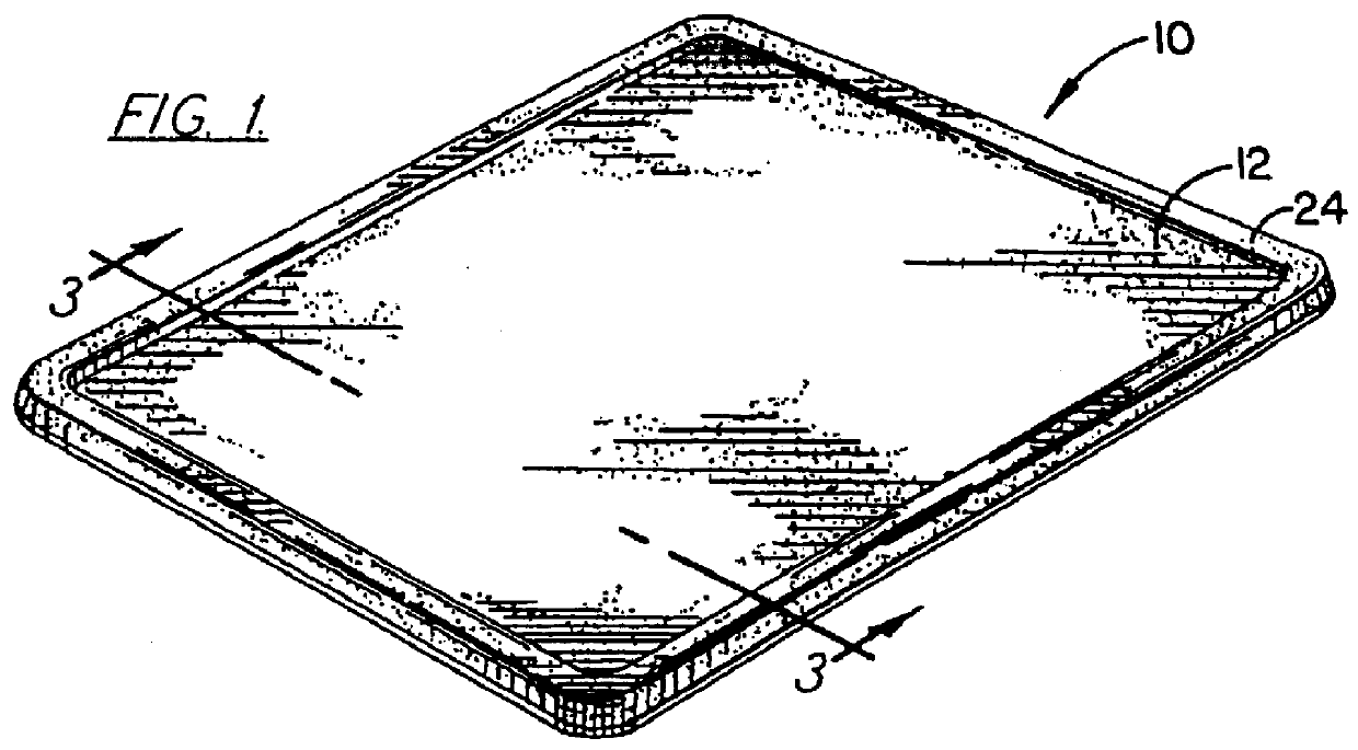
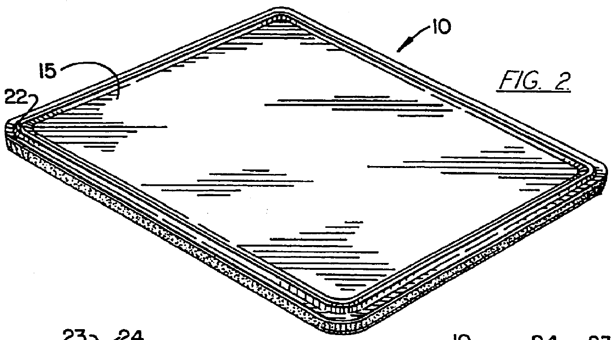
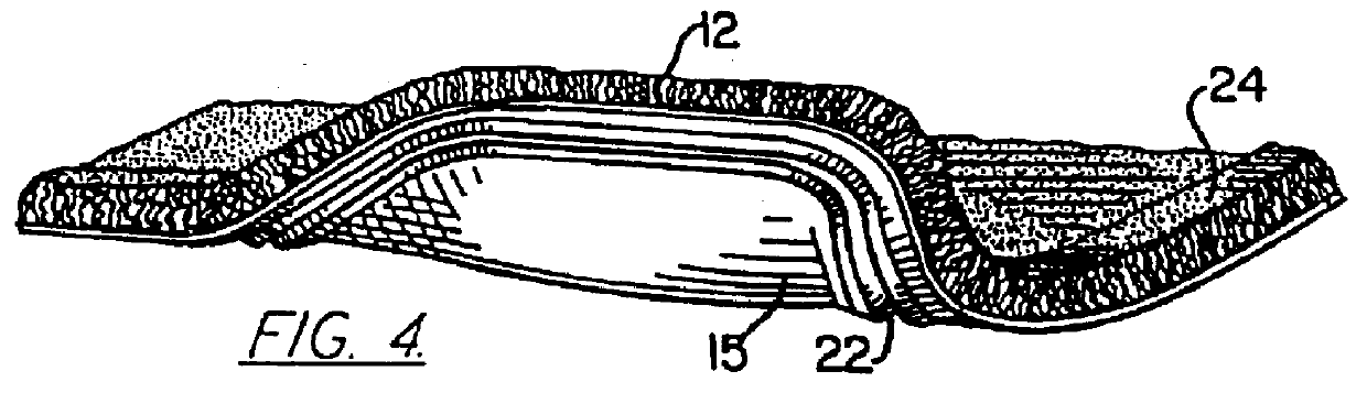
Referring now more particularly to the drawings, the pliable multilayer floor mat of the present invention is indicated generally by the numeral 10. The term "pliable" relates to the mat being easily folded or flexed and is illustrated in FIG. 4. For example, a floor mat held at arm's length which is unable to support its own weight would be pliable or a mat which can be rolled up would be pliable. The floor mat includes an upper face layer 12 overlying a base layer 15 the base layer 15 having an upper ...


PUM

PropertyMeasurementUnit
Angleaaaaaaaaaa
Angleaaaaaaaaaa
Molding pressureaaaaaaaaaa

Abstract

The floor mat of the present process is a pliable multilayer structure having an upper face layer and a base layer. The base layer has a main body section bordered by an edge section. Preferably, the main body section is relatively thin and the edge section is relatively thick. A surface of the base layer is adapted to confront flooring overlaid by the mat. The edge section has a channel extending longitudinally thereof, and preferably opening from the bottom surface of the edge section. A portion of the main body section can have a channel molded therein such that a portion of the main body section is disposed above the remainder of the main body section to provide a decorative and aesthetically pleasing design in the main body section.

Description

BACKGROUND OF THE INVENTIONThis invention relates to floor mats such as those used in the passengercompartments of automobiles or as entry mat in homes or workplaces.Floor mats of this type found in automobiles or homes generally are made of a combination of an elastomeric material (e.g., rubber) and a carpeted material. Typically the carpeted material is attached to a rubber backing layer by any of various methods. Unfortunately the layers of these mats tend to separate at the edges of the mat when the mat is in use.Various methods have been used to provide additional strength to the attachment between layers of the mat to prevent the separation of the mats layers at the edge. For example, methods include surging yarn over the edges of the mat or a tape may be placed covering the edge of the mat and then stitched to the mat. A disadvantage of these methods is that the stitching holding the edging tape to the mat also tends to wear out with use and the tape separates from the mat. F...

Claims


Application Information

Patent Timeline
IPC IPC(8): A47L23/00A47L23/26B29C43/18B29C59/02B60N3/04B29C67/00B29D99/00
CPCA43B3/0078A47L23/266B29C43/18B29C59/025B29C67/0044B29D99/0057B60N3/044B60N3/048A43B23/24Y10T428/24777B29K2995/0026B29L2031/3017B29L2031/7324Y10T428/24785Y10T428/24488Y10T428/24198Y10T156/1039Y10T428/23907Y10T428/23929Y10T428/23936Y10T428/23979A47G27/00
Inventor REUBEN, HAROLD
Owner AURIA SOLUTIONS UK I LTD
Why Eureka
Try Eureka