
Instrument head single loader

a single-loading, instrument head technology, applied in the field of medical instruments, can solve problems such as blind spots in the field of view, inability to reach, and heat produced at the tip of the scope, and achieve the effects of long recovery time, increased infection propensity, and large scars

Active Publication Date: 2018-06-19
NEW WAVE ENDO-SURGICAL CORP
View PDF7 Cites 1 Cited by
  • Summary
  • Abstract
  • Description
  • Claims
  • Application Information

AI Technical Summary

Benefits of technology

The patent text describes a need for smaller and more specialized tools in surgery procedures that require direct visualization and minimize the use of additional trocars inserted into the abdominal cavities of patients. There is also a need for innovative means and techniques for inserting medical instruments devices used in needlescopic surgery that can be properly oriented for quick attachment and detachment while maintaining direct visualization throughout. The technical effects of this patent text are to provide a solution for effectively attaching and securing full-sized laparoscopic instrument heads to small diameter instrument shafts within the body while under direct visualization and minimizing the number and size of incisions performed for each procedure.

Problems solved by technology

This approach was not practical because of its limitations of maintaining a heated light source, but it was the predecessor of today's laparoscopes and at the time the first device to inspect the interior of a human body.
Thereafter, in 1911. the first Laparoscopy was performed on a human by the Swedish Doctor H. C. Jacobeus. In spite of the technical advances that were being made, problems persisted with the heat produced at the tip of the scope when a flame was used for lighting and visualization problems such as blind spots in the field of view.
These problems limited the use of Laparoscopy.
As surgeries kept evolving, limited interest was focused on minimally invasive type surgeries.
However, the problem associated with this new type of procedure is the limited functionality of the insertion instrument.
As the instruments became thinner, the heads of the instruments became smaller and less effective to manipulate tissues and organs.
For this reason, among others, needlescopic surgery is not functional for most procedures and has not been widely adopted by the surgical community.
The problems associated with this procedure are first in the level of complexity for each procedure versus the traditional laparoscopic procedure, the lack of functionality of the smaller tools, and the very tight working area.
It is usually limited to only 3 very small instrument devices which often lack the full functionality required by traditional surgeons.
Some of the problems associated with this type of surgery are that the number of instrument heads used is usually limited to only one, not all areas of the body are accessible, and since most views are two dimensional there are special orientation problems.
An additional problem associated with both Single Incision Laparoscopic Surgery (SILS) and Natural Orifice Transluminal Endoscopic Surgery (NOTES) are their lack of ability to achieve triangulation.
When this ability is lost, it is difficult to effectively perform these types of surgeries.
People have experimented with the concept of attaching larger instrument heads to thin shafts inside the body, but no effective method has been developed or invented to facilitate the insertion and attachment of such instrument heads within the body especially under direct visualization.
In the specialized field of needlescopic surgery the instrument heads are often too small and lack functionality.
Visualization of the attachment process is also a problem that has limited the internal attachment process to an external one.
The challenge has been in finding a means of inserting, removing and remotely attaching a normal sized medical instrument head inside the abdomen of a patient.

Method used


Image

  • Instrument head single loader
  • Instrument head single loader
  • Instrument head single loader

Examples


Embodiment Construction

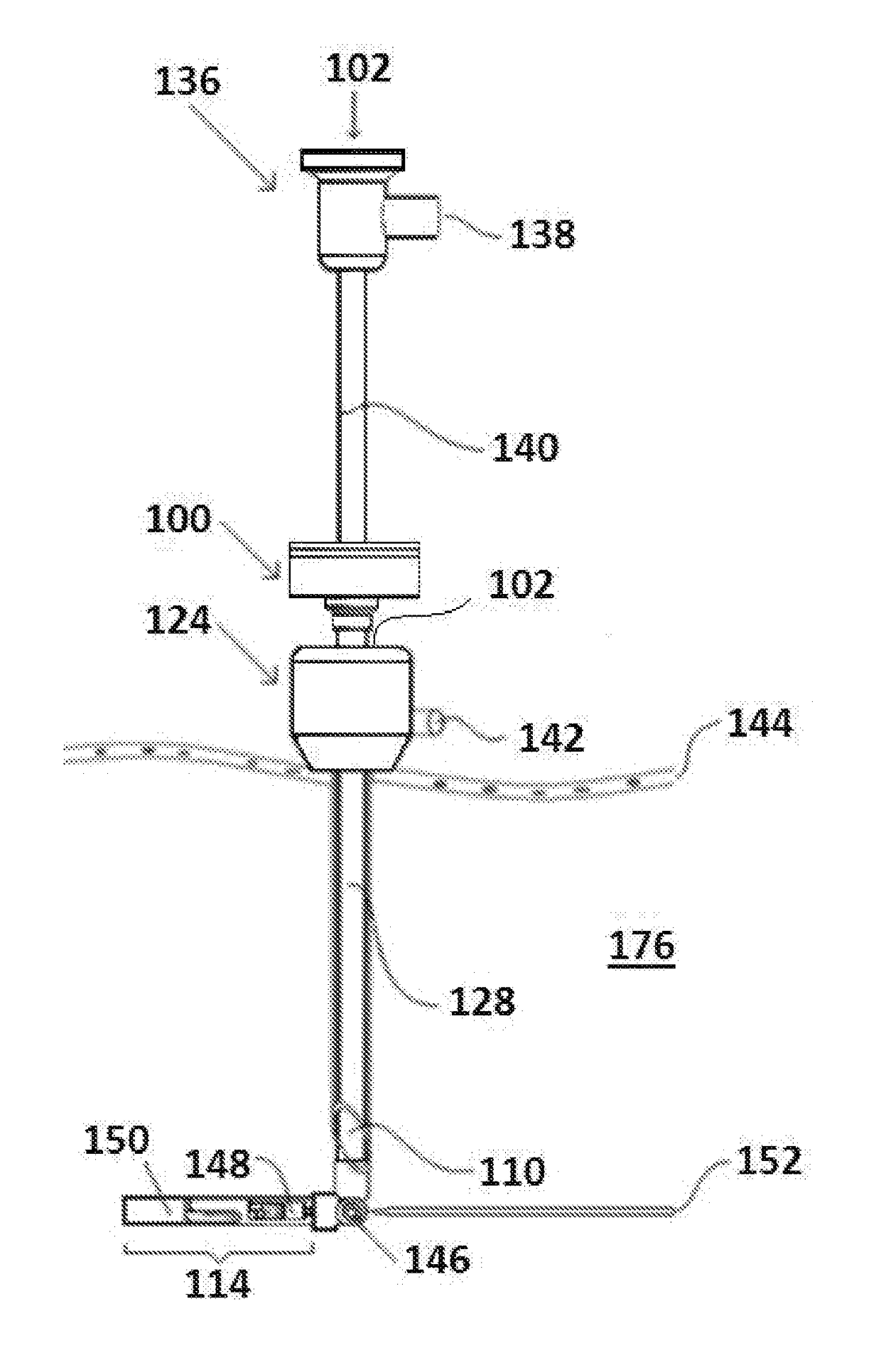
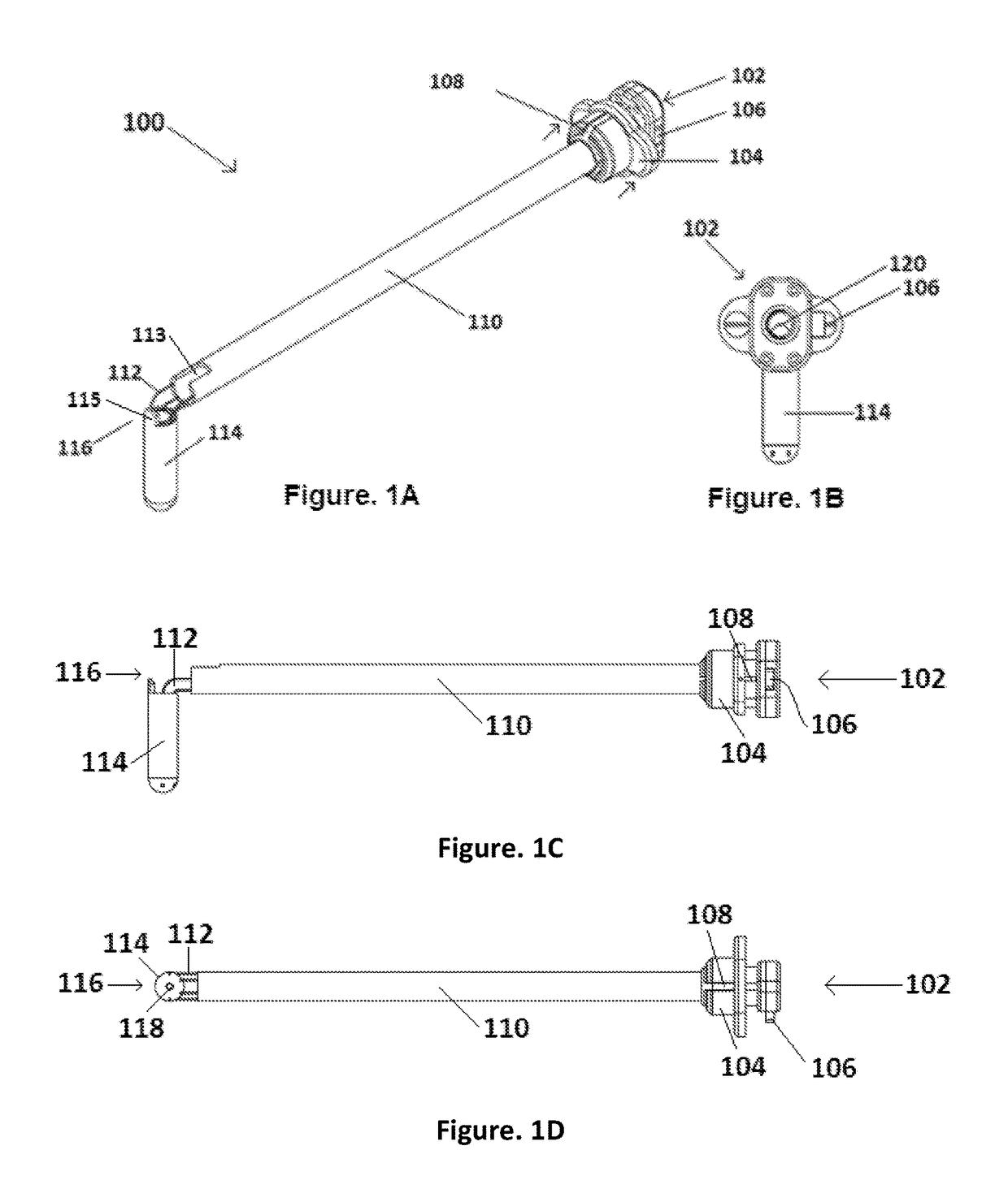
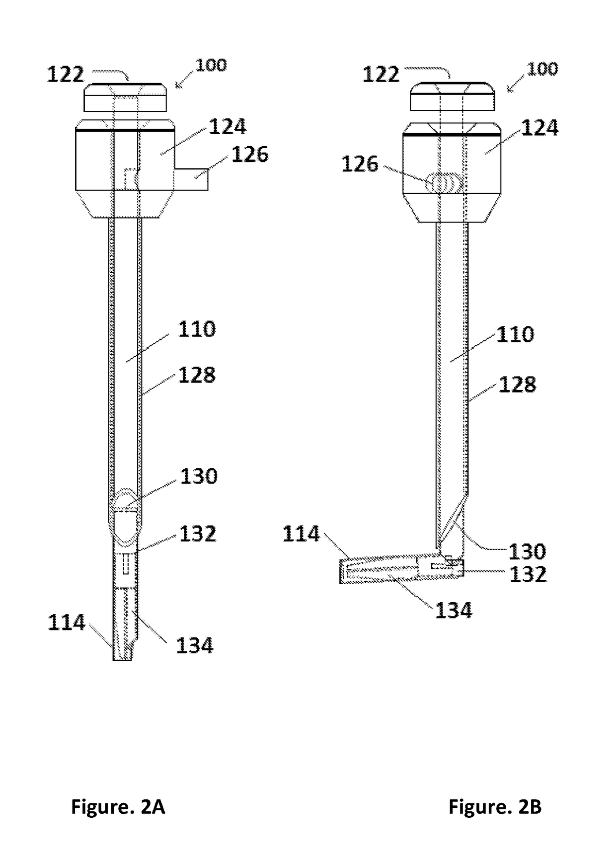
[0053]Below are exemplary implementations provided to enable persons skilled in the art to make or use the embodiments of the disclosure and are not intended to limit the scope of the disclosure, which is defined by the claims. For purposes of description herein, the terms “upper”, “lower”, “left”, “rear”, “right”, “front”, “vertical”, “horizontal”, and derivatives thereof shall relate to the invention as oriented in FIG. 1. Furthermore, there is no intention to be bound by any expressed or implied theory presented in the preceding technical field, background, brief summary or the following detailed description. It is also to be understood that the specific devices and processes illustrated in the attached drawings, and described in the following specification, are simply exemplary embodiments of the inventive concepts defined in the appended claims. Hence, specific dimensions and other physical characteristics relating to the embodiments disclosed herein are not to be considered as...


PUM


Abstract

A single instrument head loading device for use in needlescopic surgery comprises a shaft having maneuverable structure on a proximal end for use in correctly positioning an instrument head at a distal end thereof through manipulation of at least one wire engaged to a distal end loader within which the instrument head is held by maneuvering the maneuverable structure at the proximal end, to which a proximal end of the at least one wire is attached, the at least one wire traversing the length of the shaft and the distal end loader being positioned in a suitable position allowing engagement of the instrument head under continuous direct visualization to a distal end of a cooperating shaft of a surgical instrument as well as allowing for disengagement of the instrument head back into the distal end loader under continuous direct visualization, the engagement and disengagement taking place within a body cavity.

Description

CROSS REFERENCE TO RELATED APPLICATIONS[0001]This application claims priority to U.S. Provisional Application Ser. No. 62 / 269,512, filed on Dec. 18, 2015 and entitled Laparoscopic Instrument Head Single Loader, which is hereby incorporated by reference herein in its entirety.FIELD OF INVENTION[0002]The present application is directed toward medical instruments and, more particularly, to a specialized instrument head insertion device whereby attachment and detachment can take place under direct visualisation.BACKGROUND OF INVENTION[0003]Laparoscopy is a surgical procedure performed through small incisions in the abdomen whereby a trocar / cannula device is inserted to provide a means for passage of medical instruments. A thin cylindrical instrument called a laparoscope, connected to a camera, is then used to provide a clear picture of the abdominal cavity to the surgeon.[0004]Prior to starting a surgical procedure, a small incision is performed on the abdominal wall of the patient wher...

Claims


Application Information

Patent Timeline
Patent Type & Authority Patents(United States)
IPC IPC(8): A61B17/34A61M13/00A61B1/313A61B17/29A61B17/00
CPCA61B17/3423A61B1/3132A61B17/29A61M13/003A61B2017/00336A61M2202/02A61B2017/00455A61B2017/00473A61B2017/2931A61M2202/0007A61B2017/00362A61B1/00087A61B1/00154A61B1/0055A61B1/0057
Inventor HECK, SANDY LAWRENCECONLEY, ERIC WILLIAMGOMEZ, RICARDO ALEXANDER
Owner NEW WAVE ENDO-SURGICAL CORP
Learn More