Coating of a turbine engine part by overinjection

a technology of turbine engines and coatings, applied in the field of gas turbine engines, can solve the problems of difficult control of the thickness of film and glue, difficult to reproduce the application method of surface coatings to these different pieces, and complicated application of coatings, etc., and achieves the effects of easy reproducibility, good cohesion, and moderate cos

Active Publication Date: 2018-06-05
SAFRAN +1
View PDF5 Cites 0 Cited by
  • Summary
  • Abstract
  • Description
  • Claims
  • Application Information

AI Technical Summary

Benefits of technology

[0009]An aim of the invention is therefore to propose a method for applying a protective coating to a surface of a piece which is easily reproducible, in particular making it possible to obtain a given thickness for the coating, and which guarantees good cohesion between the piece to be protected and its coating, without risking damage onto the piece, while being of moderate cost, simpler and faster to make, and more environmentally friendly.

Problems solved by technology

Such composite material pieces can have complex geometry and can in particular comprise static vanes (guide vanes of the fan), movable vanes (fan vanes), or else casings, which complicates the application of their coating.
Currently methods for applying surface coatings to these different pieces are hard to reproduce.
However, the thickness of the film and the glue is very hard to control, particularly by reason of the complicated geometry of the pieces, so that the dimensions of the final piece can vary greatly from one piece to the next.
Moreover, their surface must be prepared beforehand for gluing the film by abrasion, specifically because of the material forming these pieces, which has a tendency to locally degrade the piece, to reduce the reproducibility of the method even further, and to increase the cost and duration of the method.
The choice of glue to be used is moreover made difficult insofar as the glue must observe two sometimes contradictory conditions.
It is therefore necessary to find a compromise between the preservation of the piece (lowest possible use temperature) and the properties of the glue (high temperature) to obtain optimal performance for the final piece, which in practice turns out to be difficult.
Finally, these known methods have the drawback of being polluting and requiring many expensive and bulky tools in order to observe environmental regulations concerning the protection of the operator, the limitation of volatile substances in the atmosphere etc.
However, this tool does not make it possible to apply a protective coating to a surface of a piece that is easily reproducible.

Method used


Image

  • Coating of a turbine engine part by overinjection
  • Coating of a turbine engine part by overinjection
  • Coating of a turbine engine part by overinjection

Examples


Embodiment Construction

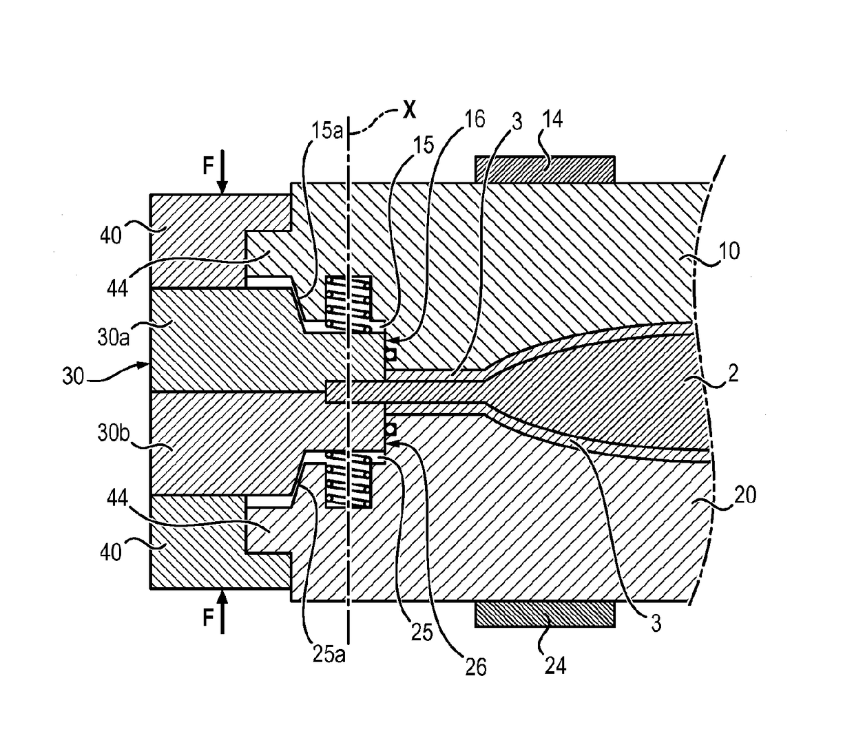
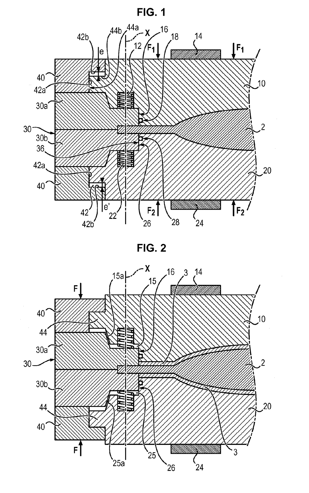
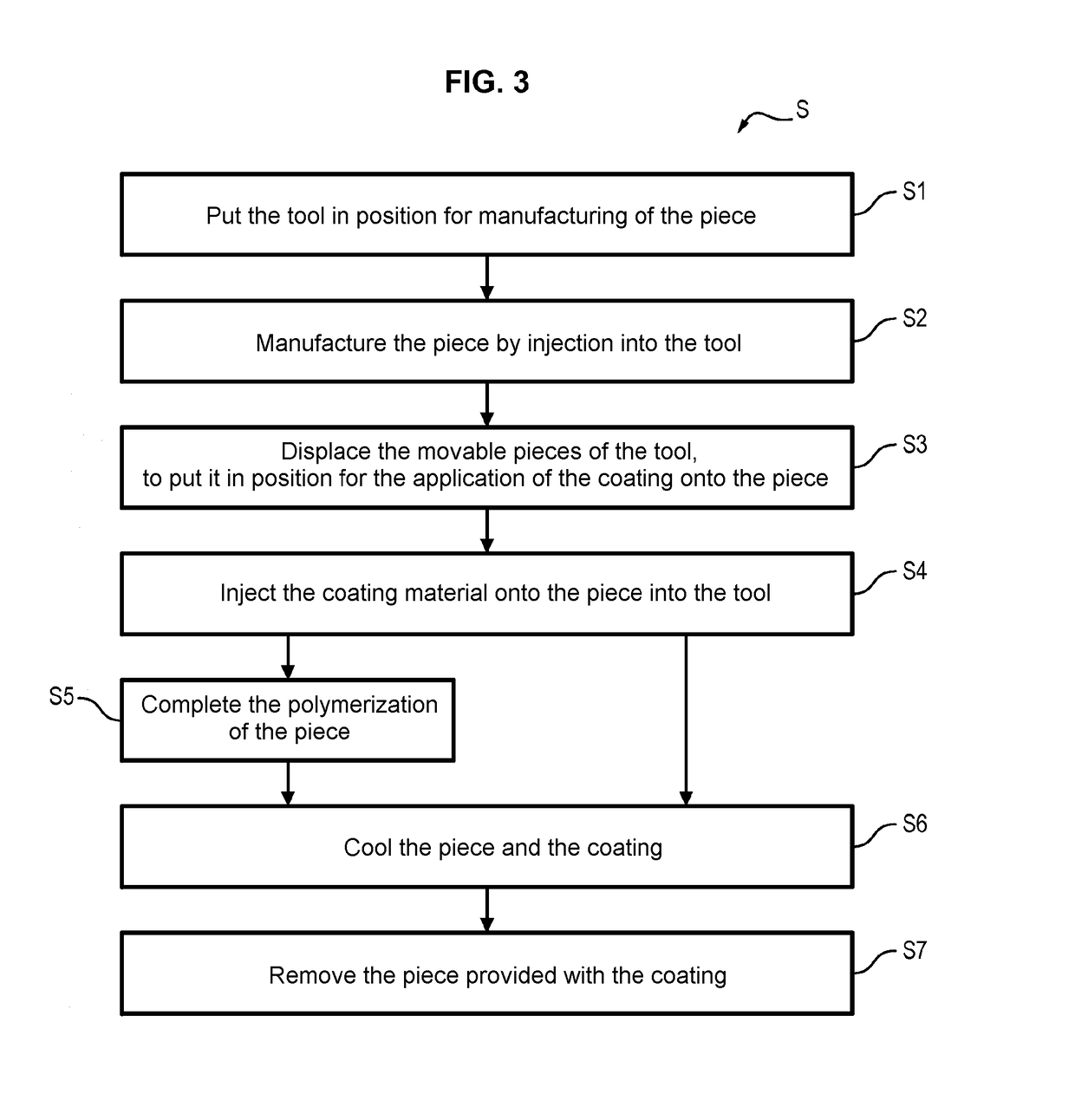
[0033]In the following, the invention will be described more specifically in the context of the manufacturing S by injection molding of a piece 2 of a gas turbine engine, including a composite material comprising a fiber reinforcement densified by a matrix, one surface of which is covered by a protective coating 3. This is however not limiting, insofar as the invention also covers the case in which the pieces 2 comprise another thermoformable material which can be injected into a tool by an injection molding method, as well as the manufacturing S of pieces 2 which are not necessarily intended to be integrated into a gas turbine engine.

[0034]The piece 2 can in particular be a static vane (guide vane, nozzle vane), a movable vane (fan vane), or else a casing.

[0035]Here, the piece 2 is made of a composite material, i.e. the component material of which comprises a fiber reinforcement densified by a matrix. The fiber reinforcement of the piece 2 comprises fibers, particularly of carbon, ...


PUM

PropertyMeasurementUnit
thicknessaaaaaaaaaa
thicknessaaaaaaaaaa
degree of polymerizationaaaaaaaaaa

Abstract

The invention relates to equipment (1) for manufacturing a part (2) by injection moulding, including: a first cavity (10), a second cavity (20), and a supporting element (30), shaped such as to hold the part (2) in position in the equipment, and defining, together with the cavities (10, 20), an inner space of the equipment, the holding element (30) as well as the first cavity (10) and / or the second cavity (20) being movable relative to one another.

Description

FIELD OF THE INVENTION[0001]The invention relates in a general manner to gas turbine engines, and more specifically the application of a protective coating to the surface of pieces belonging to such engines, particularly vanes or casings made of composite material.TECHNOLOGICAL BACKGROUND[0002]A gas turbine engine typically includes a nacelle that forms an opening to allow a determined stream of air to enter into the engine itself. The turbojet comprises a fan, adapted for providing initial compression of the air entering the engine, and one or more sections compressing the air allowed into the engine (generally a low-pressure section and a high-pressure section). The air thus compressed is allowed into the combustion chamber and mixed with fuel before being burned therein. The hot combustion gases arising from this combustion are then relaxed in different turbine stages (generally a low-pressure section and a high-pressure section).[0003]Certain pieces of the engines comprise a pro...

Claims


Application Information

Patent Timeline
Patent Type & Authority Patents(United States)
IPC IPC(8): B29C45/14B29C45/56B29L31/00
CPCB29C45/14065B29C45/14631B29L2031/7504B29C2045/14163B29C45/56
Inventor TELLIER, FLORIANFOUSSARD, OLIVIER
Owner SAFRAN
Why Eureka
Try Eureka