
Troposcatter communications system

Active Publication Date: 2018-05-22
MAHONEY PAUL F
View PDF16 Cites 2 Cited by
  • Summary
  • Abstract
  • Description
  • Claims
  • Application Information

AI Technical Summary

Benefits of technology

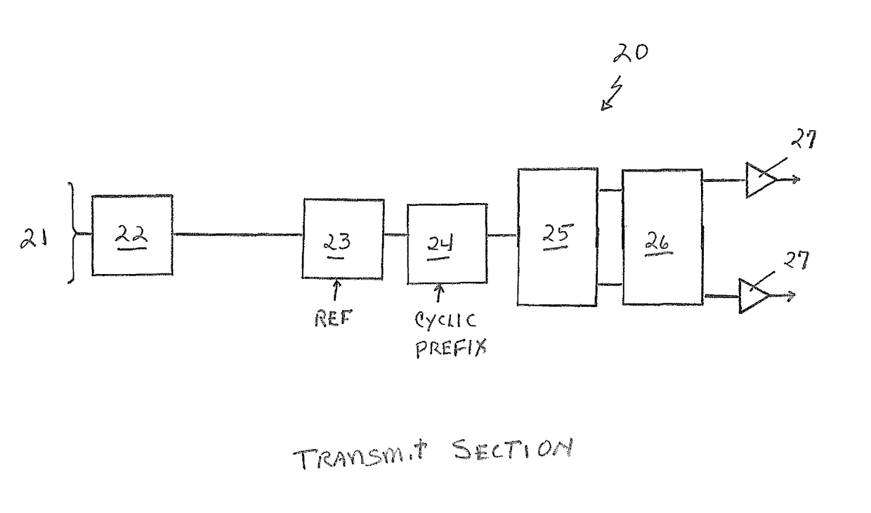
The invention provides a new way to implement troposcatter transmitters and receivers that improve performance and reduce cost, size, weight, and power. The technique involves processing in the frequency domain, which has significant advantages. The invention also introduces three techniques: achieving diversity, frequency domain equalization, and timing. The invention uses a frequency domain equalizer to improve signal quality and eliminate distortion caused by aircraft echo. The bandwidth allocation for achieving diversity is larger than the signal bandwidth, and the system uses a single high power amplifier. The invention also uses two loops for acquisition and tracking, and a coarse timing discriminator for accurate synchronization. Overall, the invention provides better performance, higher data rates, and reduced latency and bit error rates at lower cost and higher portability.

Problems solved by technology

Troposcatter systems that operate near airports are often disturbed by aircraft.
This happens because the time domain systems have a limited delay span over which they can operate.
QPSK is desirable because high power amplifiers are required and these are expensive.
For high data rate systems T can be very small meaning the signal is highly distorted even for moderately distorted channels.
As data rates go up the channels become more and more difficult to equalize and the ability to handle very dispersive links limits the performance of these systems.
For time domain systems the signal processing load becomes very large as the data rate goes up.
When 2sigma / T is larger than the number of taps, the system will fail.
However a difficulty comes up when the channel fades towards zero; dividing the signal by very small numbers causes the noise to become very large.

Method used


Image

  • Troposcatter communications system
  • Troposcatter communications system
  • Troposcatter communications system

Examples


Embodiment Construction

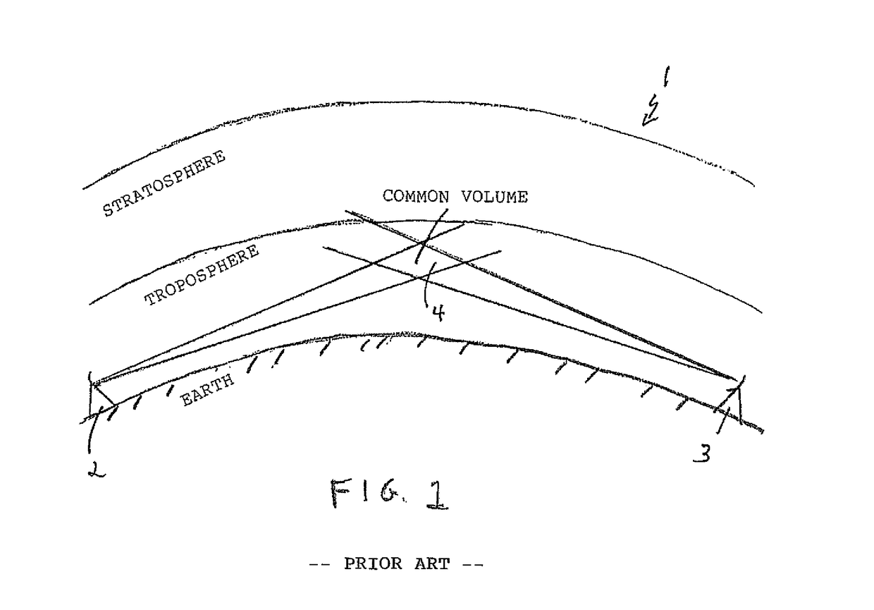
[0036]Referring to the drawings in detail wherein like elements are indicated by like numerals. There is shown in FIG. 1 a basic troposcatter communications system 1, comprised of at least one transmitter 2 and one receiver 3 aimed at a common point, termed the common volume 4, in that atmospheric area above the earth, termed the troposphere.

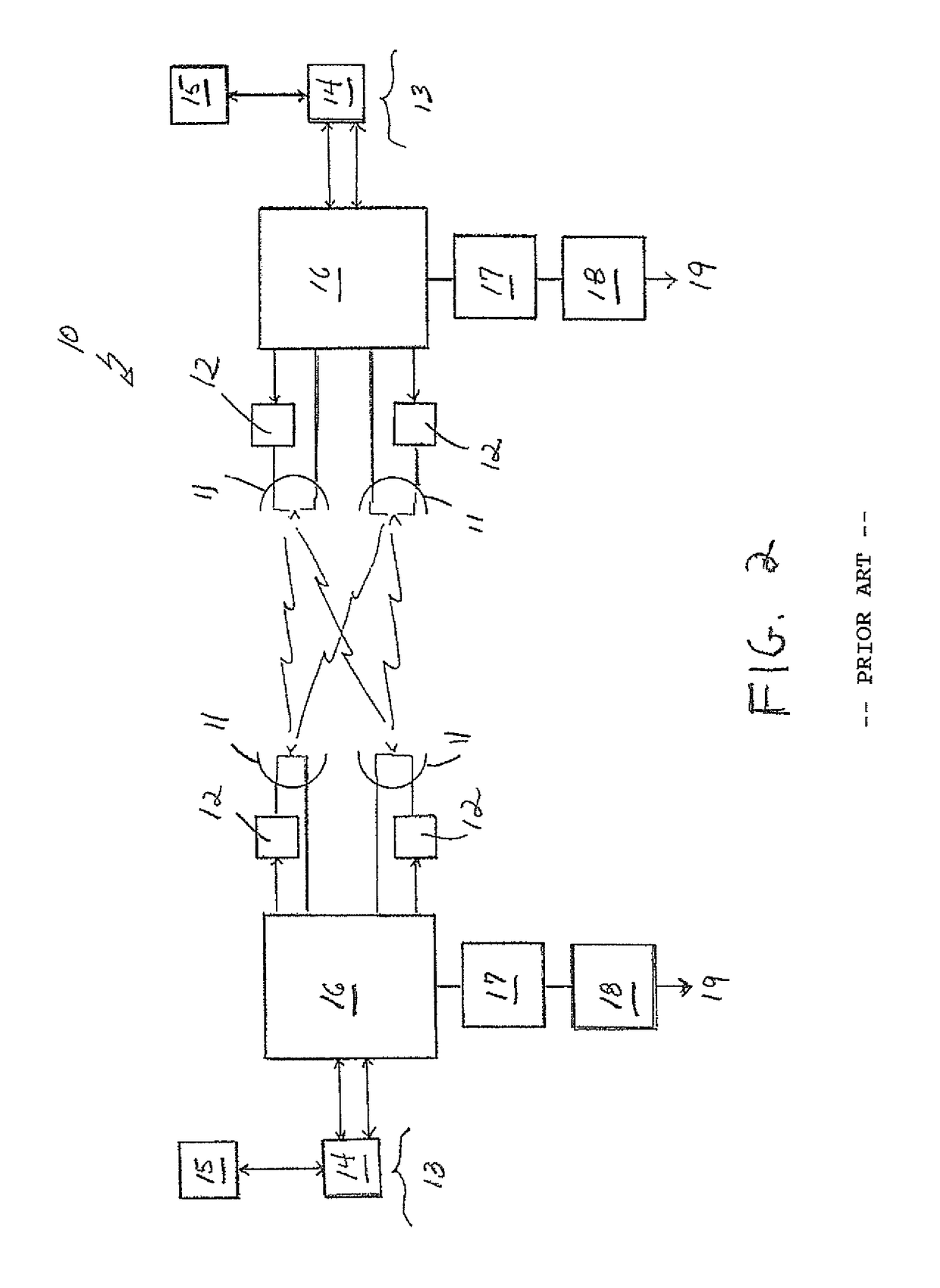
[0037]FIG. 2 shows a quad diversity system 10 where there are two power amplifiers 12 at each end and two antennas 11 on each end to produce four copies of the signal at each end. Thus it is a quad diversity system. The antennas each receive signals from both power amplifiers. The antennas are spaced far enough away so that the signal from each power amplifier fades independently of the other. This is the most common troposcatter configuration. User traffic 13 enters and is received from the system 10 through a troposcatter modem 14 having external monitoring and control 15. The troposcatter modems 14 pass and receive data through a dual and qua...


PUM


Abstract

A method of implementing troposcatter communications is provided. Transmittal of signals between receive and transmit antennas is performed in the time domain. After reception of a transmitted signal, the signal is converted to the frequency domain for signal processing. After signal processing, the signal is converted back into the time domain.

Description

CROSS-REFERENCE TO RELATED APPLICATIONS[0001]Applicant claims the priority benefits of U.S. Provisional Patent Application No. 62 / 096,145, filed Dec. 23, 2014.BACKGROUND OF THE INVENTION[0002]This invention relates to communications systems, and in particular to troposcatter communications systems.[0003]Troposcatter radio links have been in use for more than 60 years. The early systems used FM / FDM modulation which were limited to a couple of dozen voice channels. These links were used by commercial carriers across the southern USA. The DEW line in Alaska, Northern Canada and Greenland used Tropo radios also. Many militaries have Troposcatter radio systems. Troposcatter links are used to communicate to offshore locations such as oil platforms or offshore islands. These systems can transmit data over the horizon usually at distances from 25 to 200 miles; a few links operate up to 400 miles. The advantage of Troposcatter systems is that they can be quickly set up and they provide relia...

Claims


Application Information

Patent Timeline
IPC IPC(8): H04B7/22
CPCH04B7/22H04B7/14
Inventor MAHONEY, PAUL F
Owner MAHONEY PAUL F
Learn More