
Joint movement analysis system and method; knee-joint dynamic evaluation method and system

Active Publication Date: 2018-11-22
SHANGHAI INNOMOTION
View PDF0 Cites 4 Cited by
  • Summary
  • Abstract
  • Description
  • Claims
  • Application Information

AI Technical Summary

Benefits of technology

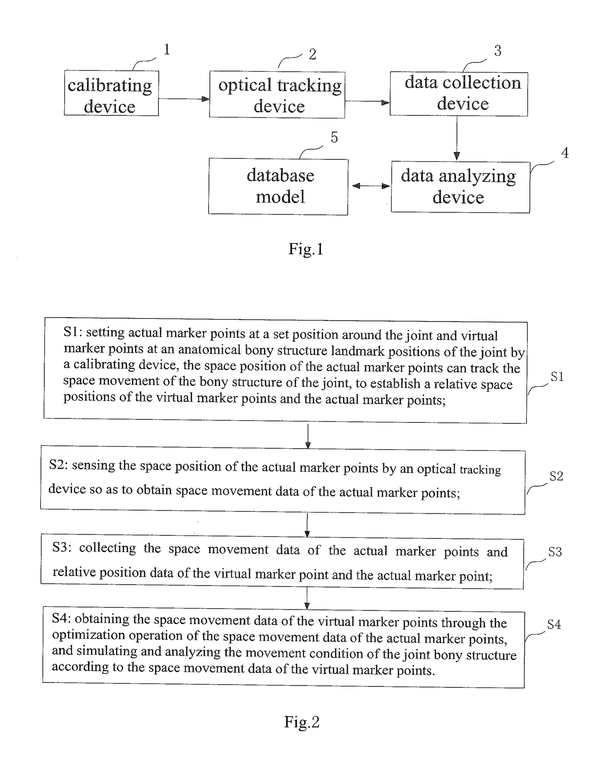
The present invention has the following benefits compared to previous techniques: actual marker points are placed around a joint, and their number and distribution are determined based on the joint's bone structure and space position. This allows the marker points to track the joint's movement and provide a reference point for positional changes. The data captured by optical tracking devices is used to analyze and optimize the movement of joints, resulting in dynamic analysis and ensuring the best test position and data stability during movement.

Problems solved by technology

The analysis result is a static image and cannot track the joint movement and abnormal results caused by joint movement.
The test results are subjective and qualitative based on externally imposed motions, and can not quantitatively track a actual movement of the joint.
All of the above methods can not detect and analyze the movement of the joint dynamically and objectively.
However, the multiple cameras must be systematically calibrated before testing, and a large floor space is required for equipment placement, so the analysis is very inconvenient.

Method used


Image

  • Joint movement analysis system and method; knee-joint dynamic evaluation method and system
  • Joint movement analysis system and method; knee-joint dynamic evaluation method and system
  • Joint movement analysis system and method; knee-joint dynamic evaluation method and system

Examples


Embodiment Construction

[0042]In order to make the above objects, features, and advantages of the present invention more apparent, the specific embodiments of the present invention are described in detail below with reference to the accompanying drawings.

[0043]In the following description, numerous specific details are set forth in order to provide a thorough understanding of the present invention. However, the present invention can be implemented in many other manners different from those described herein, and those skilled in the art can make similar extensions without departing from the essence of the present invention. Therefore, the present invention is not limited by the specific embodiments disclosed below.

[0044]The joint movement analysis system of the present invention can objectively and dynamically analyze the joint movement condition, and the established simulation data can truly track the joint movement condition. When used in the clinic, it can provide a judgment basis for the diagnosis of jo...


PUM


Abstract

A joint movement analysis system is provided in the present invention, comprising a calibrating device which is used for setting connections between actual marker points around a joint and virtual marker points at the anatomical bony landmark positions of the joint to track the space movement of the joint; an optical tracking device which is used for sensing the space position of the actual marker points so as to obtain the space movement data of the actual marker points; a data collection device which is used for collecting the space movement data of the actual marker points and the space relative position data of the virtual marker points with respect to the actual marker points; a data analyzing device which is used for obtaining the space movement data of the virtual marker points by optimization operating of the movement data of the actual marker points, and simulating and analyzing the movement condition of the joint bony structure according to the space movement data of the virtual marker points. The invention can dynamically analyze the joint movement condition, and the analysis result can track the actual joint condition objectively, quantitatively and accurately.

Description

TECHNICAL FIELD[0001]The invention belongs to the field of signal detection and processing, and in particular relates to a joint movement analysis system and method.BACKGROUND ART[0002]It is necessary to understand a joint movement in many fields, for example, in the fields of bionics, medicine, etc. to establish a bionic model by understanding the joint movement, to design the other bionic devices, or diagnose the joint by observing the joint movement in the field of medicine. Especially for the movement of human joints, such as knee, ankle, hip, wrist, elbow and shoulder, the analysis and evaluation of the movement of these joints have great significance.[0003]The traditional medical joint analysis methods are static analysis methods, such as magnetic resonance imaging (MM), X-ray imaging (X-ray), spiral tomography (CT) and other imaging analysis methods. The analysis result is a static image and cannot track the joint movement and abnormal results caused by joint movement. There ...

Claims


Application Information

Patent Timeline
IPC IPC(8): A61B5/11A61B5/00A61B90/00
CPCA61B5/1127A61B5/1121A61B5/4528A61B90/39A61B5/0075A61B2560/0223A61B2090/397G16H50/50
Inventor WANG, SHAOBAISUN, FANGWANG, HUI
Owner SHANGHAI INNOMOTION
Learn More