
Device and method for synthesis of a polymer under separation of a gaseous substance

a gaseous substance and polymer technology, applied in the field of aliphatic or semiaromatic polyamide synthesis apparatus, can solve the problems of deterioration in product quality, foaming of polyamide melt, and deposits on the inner walls of the reactor

Active Publication Date: 2018-05-01
BASF SE
View PDF15 Cites 0 Cited by
  • Summary
  • Abstract
  • Description
  • Claims
  • Application Information

AI Technical Summary

Benefits of technology

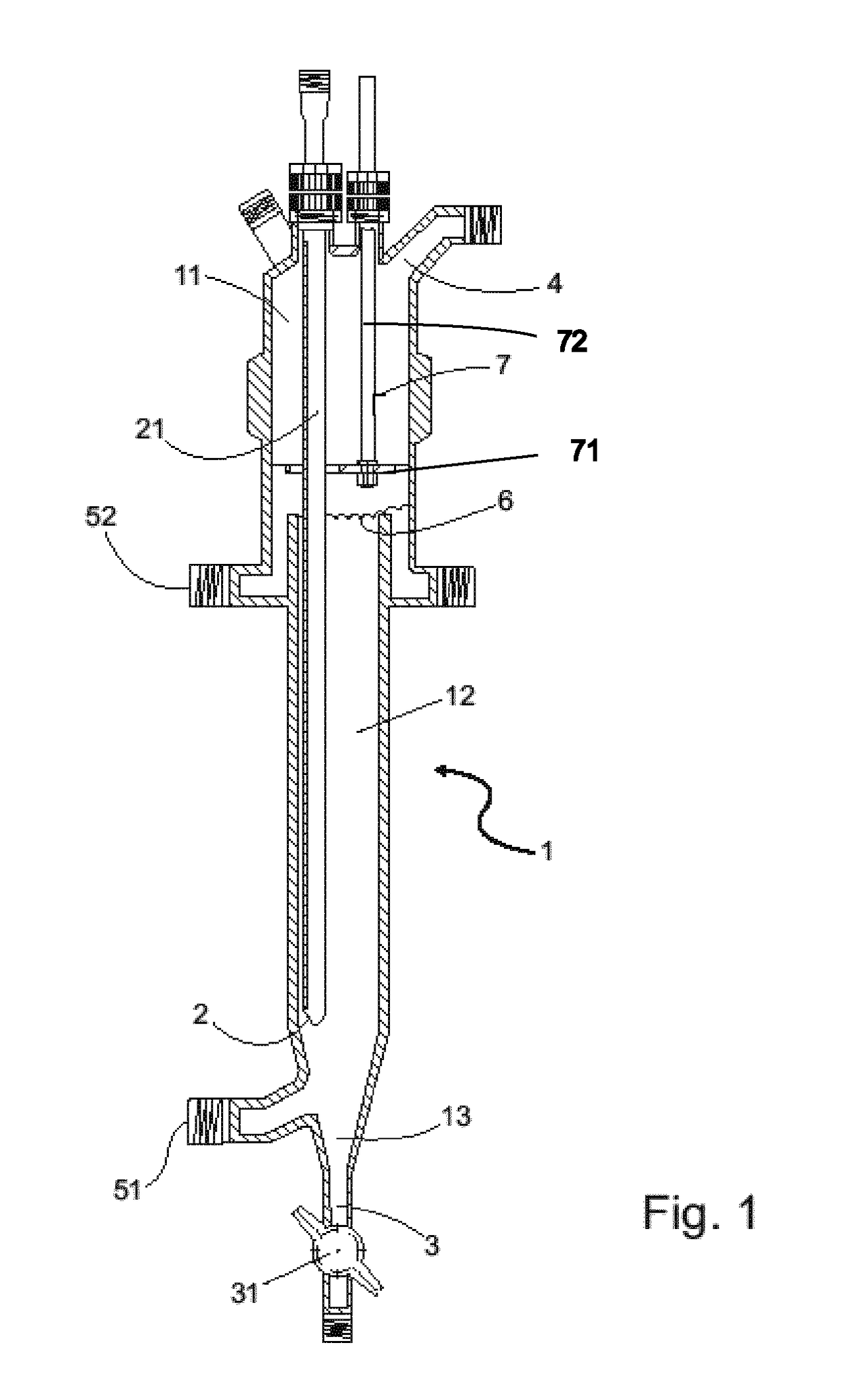
[0040]The inventive apparatus prevents the formation of deposits in the reaction space in the area between the upper section and the middle section by means of the removal device, and in the middle and any lower section by means of a homogeneous prepolymer film formed on the inner wall of the reaction space. Since it is unnecessary to stop the process to manually remove deposits, it can especially be performed continuously.
[0041]The first return orifice and the second return orifice of the inventive apparatus can especially be connected to one another by a return line in which there is disposed a pump. This is set up to transport a liquid from the first return orifice to the second return orifice. The inventive apparatus enables application of the known principle of a falling-film reactor to avoid the formation of deposits in the middle section and in the lower section, since a melt transported via the return line into the upper section can be distributed homogeneously by the distributing device over the inner wall of the middle section and to any lower section. The formation of deposits in the upper section is prevented in accordance with the invention by the movement of the removal device.
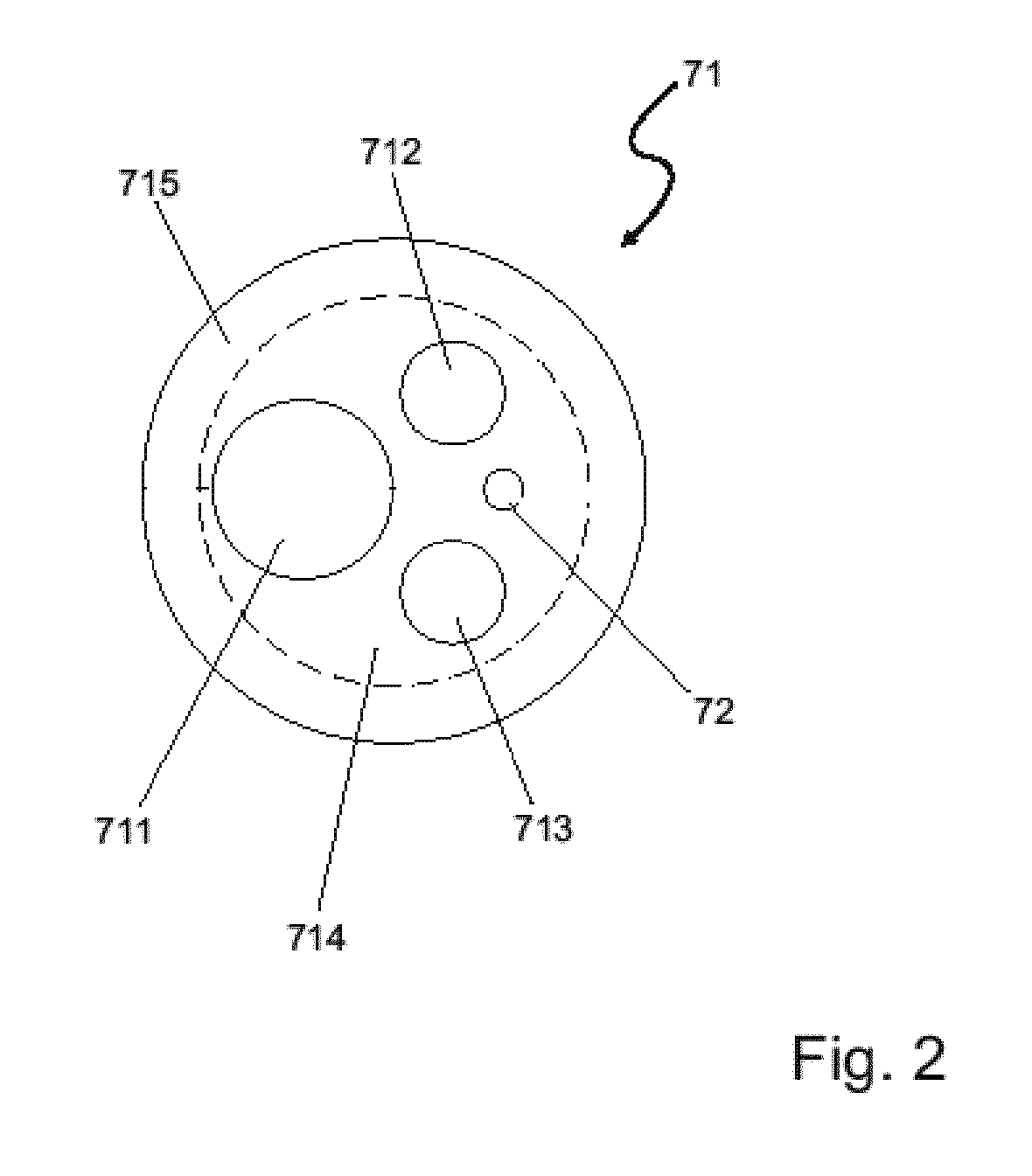
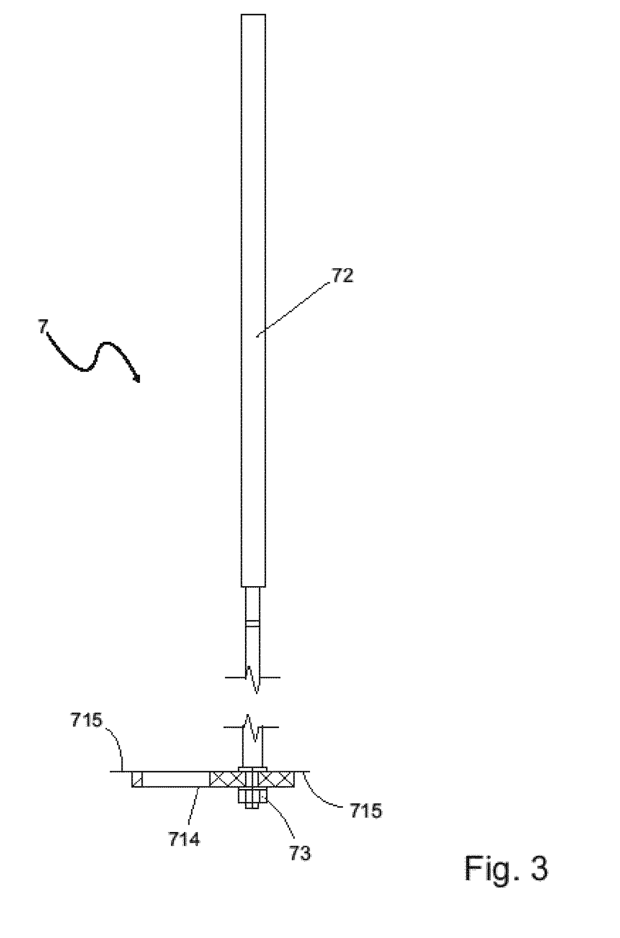
[0042]Preferably, the removal device has a removal head disposed on the inner wall at the top of the middle section. More preferably, the thickness of the removal head decreases toward at least one of its edges. In this way, flexibility of the removal head at its edges can be obtained. More preferably, the removal head has, at right angles to the direction of movement of the removal device, a cross-sectional area greater than the cross-sectional area at the top of the middle section at right angles to the direction of movement of the removal device. The removal head can also make contact with the inner wall at the top of the middle section with deformation of its edges, as a result of which a high pressure is exerted on the inner wall of the reaction space and it is possible to remove even very stubborn deposits. Particularly preferably, the removal head has, at right angles to the direction of movement of the removal device, a cross-sectional area which covers at least the cross-sectional area of an inlet line at right angles to the direction of movement of the removal device. The removal head preferably has orifices which enable the passage of the gaseous substance. Alternatively, the removal head, in accordance with the invention. May also take the form of a knife or doctor blade. It is additionally possible that the removal device consists of a rope. The removal head allows effective elimination of the deposits on the inner wall. At the same time, the removal head itself has a minimum surface area, in order that a minimum level of deposits, if any, form on the removal head itself.
[0045]In order to avoid heat losses and, in the event of damage to the reactor, to prevent the escape of a polymer melt, the reaction space is preferably jacketed.

Problems solved by technology

In the course of this, however, deposits occur on the inner walls of the reactor above the liquid phase.
This leads to a deterioration in product quality.
However, this process has the disadvantage that steam leaves the polyamide melt through the conveying screw, which can result in foaming of the polyamide melt.
However, deposits in the reactor interior can form in this case above the inlet for the melt.
However, the apparatus used for this purpose has many moving parts and hence a high surface area, which leads to the formation of deposits.

Method used


Image

  • Device and method for synthesis of a polymer under separation of a gaseous substance
  • Device and method for synthesis of a polymer under separation of a gaseous substance
  • Device and method for synthesis of a polymer under separation of a gaseous substance

Examples


Embodiment Construction

[0037]A prepolymer in the context of the invention refers to a composition comprising polymeric compounds having complementary functional groups capable of a condensation reaction to increase the molecular weight.

[0038]The term “prepolymer melt” in the context of the present invention refers to a free-flowing composition of the respective reaction mixture comprising the prepolymers. In this context, the temperature of the prepolymer melt need not necessarily be above the melting temperature of the pure prepolymer. The flowability may also result from the presence of other components of the prepolymer melt, for example water, low molecular weight oligomers, etc. In a specific embodiment, the prepolymer itself is present in molten form in the prepolymer melt.

[0039]The figures for the number-average molecular weight Mn and for the weight-average molecular weight Mw in the context of this invention are each based on a determination by means of gel permeation chromatography (GPC). For ca...


PUM

PropertyMeasurementUnit
pressureaaaaaaaaaa
temperatureaaaaaaaaaa
viscosityaaaaaaaaaa

Abstract

The invention relates to a device for synthesis of a polymer under separation of a gaseous substance. Said device comprises a reaction chamber (1), which has a top section (11), a middle section (12) and a bottom section (13), an inlet opening (2) which is arranged in the middle section (12), a first outlet opening (3) which is arranged in the bottom section (13), a second outlet opening (4) which is arranged in the top section (11), a first return opening (51), which is arranged in the bottom section (13), a second outlet opening (52), which is arranged under the top section (11), a distribution device (6), which is arranged between the top section (11) and the middle section (12), and a removal device (7) which is arranged to be movable along the top section (11). The invention further relates to a method for synthesis of a polymer which can be carried out in said device.

Description

CROSS-REFERENCE TO RELATED APPLICATION[0001]This is the U.S. national phase of International Application No. PCT / EP2014 / 062122, filed Jun. 11, 2014, which claims the benefit of European Patent application No. 13171654.0, filed Jun. 12, 2013.BACKGROUND OF THE INVENTION[0002]The present invention relates to a process for preparing an aliphatic or semiaromatic polyamide, in which a polyamide prepolymer is subjected to a solid state polymerization.[0003]The present invention relates to an apparatus for synthesis of a polymer, especially of a polyamide, with separation of a gaseous substance, especially of water. The present invention further relates to a process for synthesizing a polymer, especially a polyamide, with separation of a gaseous substance, especially of water, which can especially be performed using the inventive apparatus.STATE OF THE ART[0004]A multitude of industrial polymers are prepared by a polycondensation in which the increase in molecular weight is accompanied by t...

Claims


Application Information

Patent Timeline
Patent Type & Authority Patents(United States)
IPC IPC(8): C08G69/30B01J19/00C08L77/06C08F2/00B01J19/18C08G69/26C08G69/28
CPCC08G69/30B01J19/0026B01J19/1881C08F2/002C08F2/005C08G69/28C08L77/06C08G69/265B01J2219/185B01J2219/00094B01J2219/00168B01J2219/00247
Inventor ZHU, NINGSTAMMER, ACHIMCLAUSS, JOACHIMKORY, GAD
Owner BASF SE
Learn More