
All-solid secondary battery

Active Publication Date: 2018-04-24
OHARA
View PDF9 Cites 0 Cited by
  • Summary
  • Abstract
  • Description
  • Claims
  • Application Information

AI Technical Summary

Benefits of technology

The present invention is about a new kind of battery made using solid state technology. The goal is to create a battery with a high capacity per unit volume and low internal resistance. The inventors found that by connecting the second electrodes layers on both sides of a first electrode layer, they could create a path for electrons to move through. This allows for the transfer of electrons in a way that increases the battery's discharge capacity. Overall, the invention provides a solution for creating efficient and effective all-solid state batteries.

Problems solved by technology

However, in the laminated structure disclosed in Patent Document 1, the current collector layer irrelative to the discharge capacity is formed in each of the negative electrode layers and the positive electrode layers, and hence it cannot be said that the discharge capacity per unit volume is sufficiently high.
In the laminated structure and manufacturing method disclosed in Patent Document 1, when a solid-electrolyte green sheet layer (a solid-electrolyte paste layer in Patent Document 1) is thinly formed and an electrode green sheet layer (a positive electrode active material paste layer or a negative electrode active material paste layer in Patent Document 1) is thickly laminated (e.g. a thickness of the order of 10 to 20 μm) on part of the above formed green sheet layer, a problem occurs where the solid-electrolyte green sheet layer is torn at the time of removing the green sheet group, following lamination, from a support such as a PET film.
On the other hand, when the thick electrode-layer green sheet is laminated over the thin solid-electrolyte green sheet, a problem occurs where the positive electrode and the negative electrode are short-circuited on the end surface of the green sheet group.
Accordingly, with the laminated structure and using the manufacturing method disclosed in Patent Document 1, it is difficult to form the electrode layer thickly while forming the solid electrolyte layer thinly, and it is thus difficult to increase the discharge capacity per unit volume.

Method used


Image

  • All-solid secondary battery
  • All-solid secondary battery
  • All-solid secondary battery

Examples


examples

[0110]Hereinafter, the present invention is described with specific examples.

(Preparation of Solid Electrolyte)

[0111]A ceramic electrolyte and a glass electrolyte were used as the solid electrolyte. Li1.3Al0.1Zr1.8Y0.1Si0.1P2.9O12 was prepared as the ceramic electrolyte.

[0112]As raw materials, powders of Li2CO3, ZrO2, Al2O3, Y2O3 and SiO2 were mixed with a H3PO4 solution at a stoichiometric ratio, and thereafter heat-treated on a platinum plate at 1480° C. for one hour. The heat-treated mixture of the raw materials was crushed into grains no greater than 200 μm by use of the stamp mill, which was mixed with φ 2 mm YTZ balls and ethanol, and crushed in a planetary ball mill. The obtained powder was dried to obtain a 1.0-μm (D50) ceramic electrolyte powder.

[0113]Li2O—Al2O3—P2O5 type glass was prepared as the glass electrolyte. The raw materials were weighed so that 50 mol % of Li2O, 9 mol % of Al2O3 and 41 mol % of P2O5 were in an oxide-converted composition and uniformly mixed, which...


PUM


Abstract

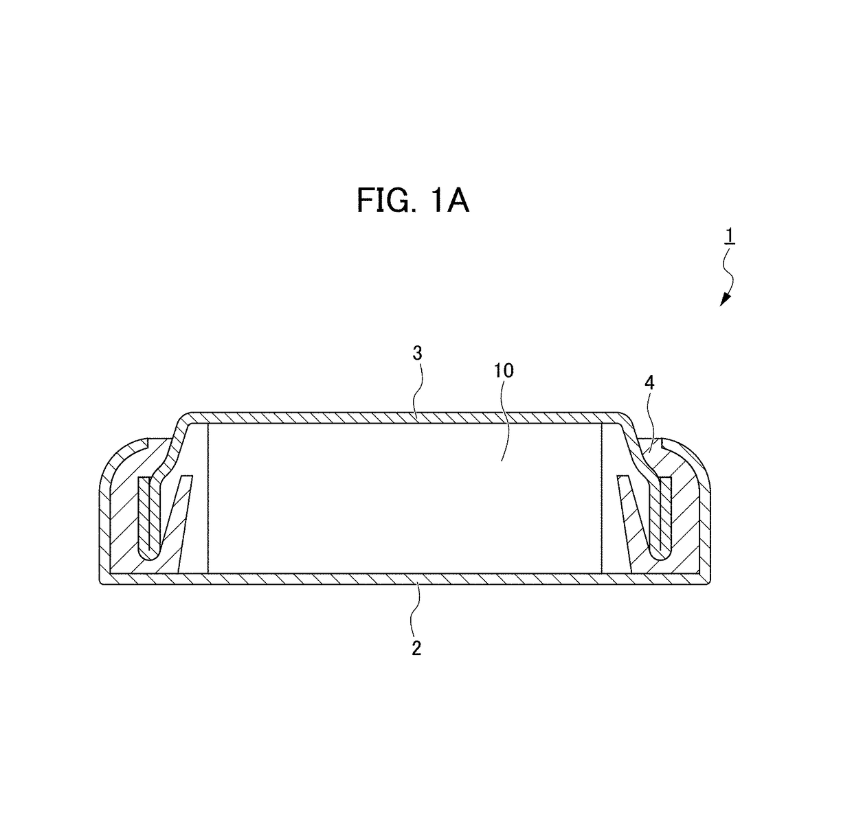
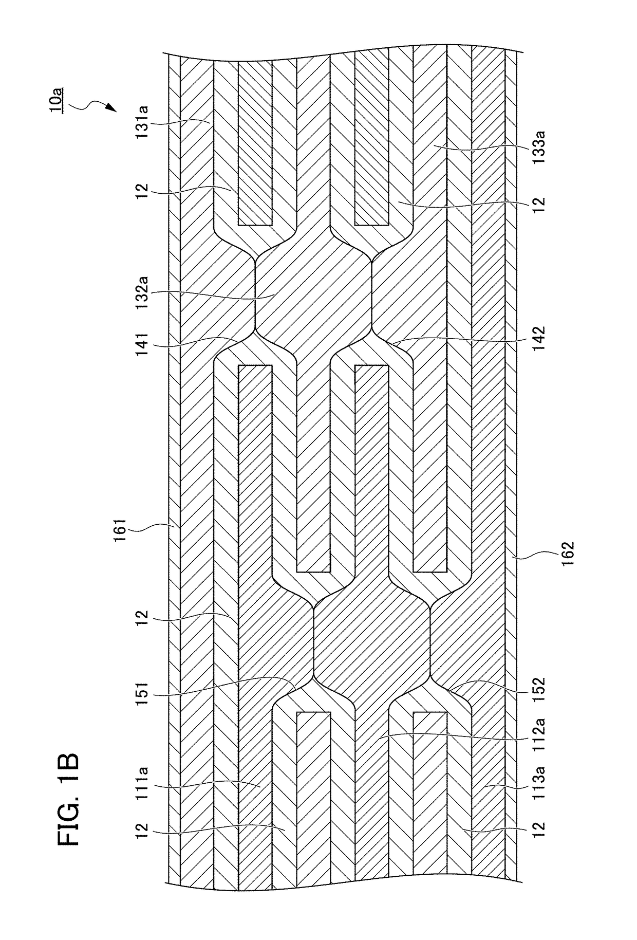
An all-solid secondary battery has first electrode layers, and second electrode layers laminated on both sides of the first electrode layer with solid electrolyte layers placed in between, wherein at least one first opening is provided which penetrates the first electrode layer and the solid electrolyte layers adjacent to the first electrode layer, and the second electrode layers present on both sides of the first electrode layer are in contact with each other on the inside of the first opening.

Description

[0001]This application is based on and claims the benefit of priority from Japanese Patent Application No. 2012-114549, filed on 18 May 2012, the content of which is incorporated herein by reference.BACKGROUND OF THE INVENTION[0002]Field of the Invention[0003]The present invention relates to an all-solid secondary battery.[0004]Related Art[0005]An all-solid secondary battery, using an inorganic solid electrolyte and not using an organic substance even for an electrode is free of problems concerning leakage of organic electrolytic solution and generation of gas from the organic electrolytic solution, and is thus expected to be a safe battery. Further, the all-solid secondary battery is less likely to produce a side reaction other than battery reactions as compared to liquid batteries, and can thus be expected to have a long operating life as compared to liquid batteries.[0006]As an example of the all-solid secondary battery, Patent Document 1 discloses one having a structure where ne...

Claims


Application Information

Patent Timeline
IPC IPC(8): H01M6/42H01M4/13H01M10/04H01M10/052H01M10/0562H01M10/0585
CPCH01M4/13H01M10/0463H01M10/052H01M10/0585H01M10/0562H01M2300/0068H01M10/0427Y02E60/10Y02P70/50H01M10/058
Inventor OGASA, KAZUHITO
Owner OHARA
Learn More