
System for visualizing a three dimensional (3D) model as printed from a 3D printer

a three-dimensional model and printer technology, applied in the field of three-dimensional (3d) printing, can solve the problems of erroneous belief among many users, the complexity of the parts that can be produced is higher, and the 3d printing now includes a more automated natur

Active Publication Date: 2018-04-17
XEROX CORP
View PDF24 Cites 10 Cited by
  • Summary
  • Abstract
  • Description
  • Claims
  • Application Information

AI Technical Summary

Benefits of technology

Enables users to visualize and correct potential printing issues before production, reducing material waste and improving the accuracy of 3D printed objects by simulating the printing process and optimizing build orientation and material usage.

Problems solved by technology

Compared to conventional manufacturing, 3D printing now includes a more automated nature in the manufacturing process, and a higher range of complexity in parts that can be produced.
Unfortunately, the democratization of additive manufacturing coupled with the feasibility of producing complex geometries has led to the widespread but often erroneous belief among many users that any model that can be designed in a computer-aided design (CAD) system can be manufactured using a 3D printer.
Poor understanding of how the printing parameters affect the printed model in relation to the original model often leads to failures that are only apparent after printing, even to experts.
As another example, service providers for 3D printed parts often have significant scrap from print failures that are a result of this poor understanding.
Furthermore, the printed size of structures, such as thin walls, bridges, and spikes, affect the integrity of these structures.
This lack of coordination between the printer-related resolutions / minimum-sizes and the numerical resolutions of the STL file leads to the discrepancies between the final 3D printed object and the designed CAD model.
Predicting and correcting defects or deficiencies saves time, material, energy, and labor by not producing parts from designs with unexpected flaws that manifest themselves in the manufacturing process.
However, the ability to manually predict and correct defects or deficiencies is becoming increasingly difficult as the number of printers, materials, and manufacturing services available grows.
Also, no realistic rendering of the material is shown.
In view of the foregoing, manufacturability analysis for 3D printing is typically restricted to preparing the model for printing.
As mentioned earlier, these tools are machine specific, making it difficult for designers to access them.

Method used


Image

  • System for visualizing a three dimensional (3D) model as printed from a 3D printer
  • System for visualizing a three dimensional (3D) model as printed from a 3D printer
  • System for visualizing a three dimensional (3D) model as printed from a 3D printer

Examples


Embodiment Construction

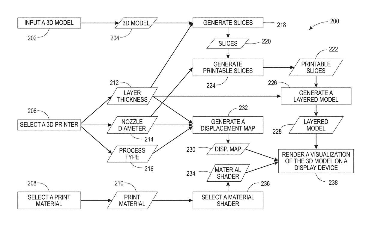
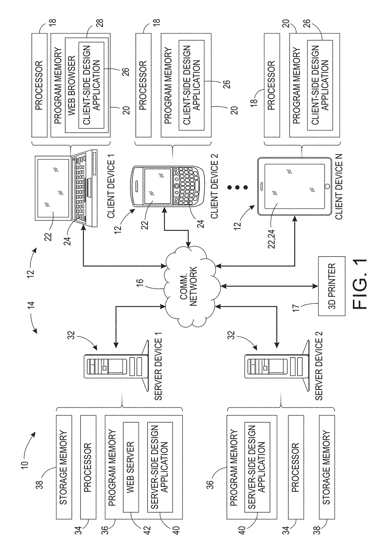
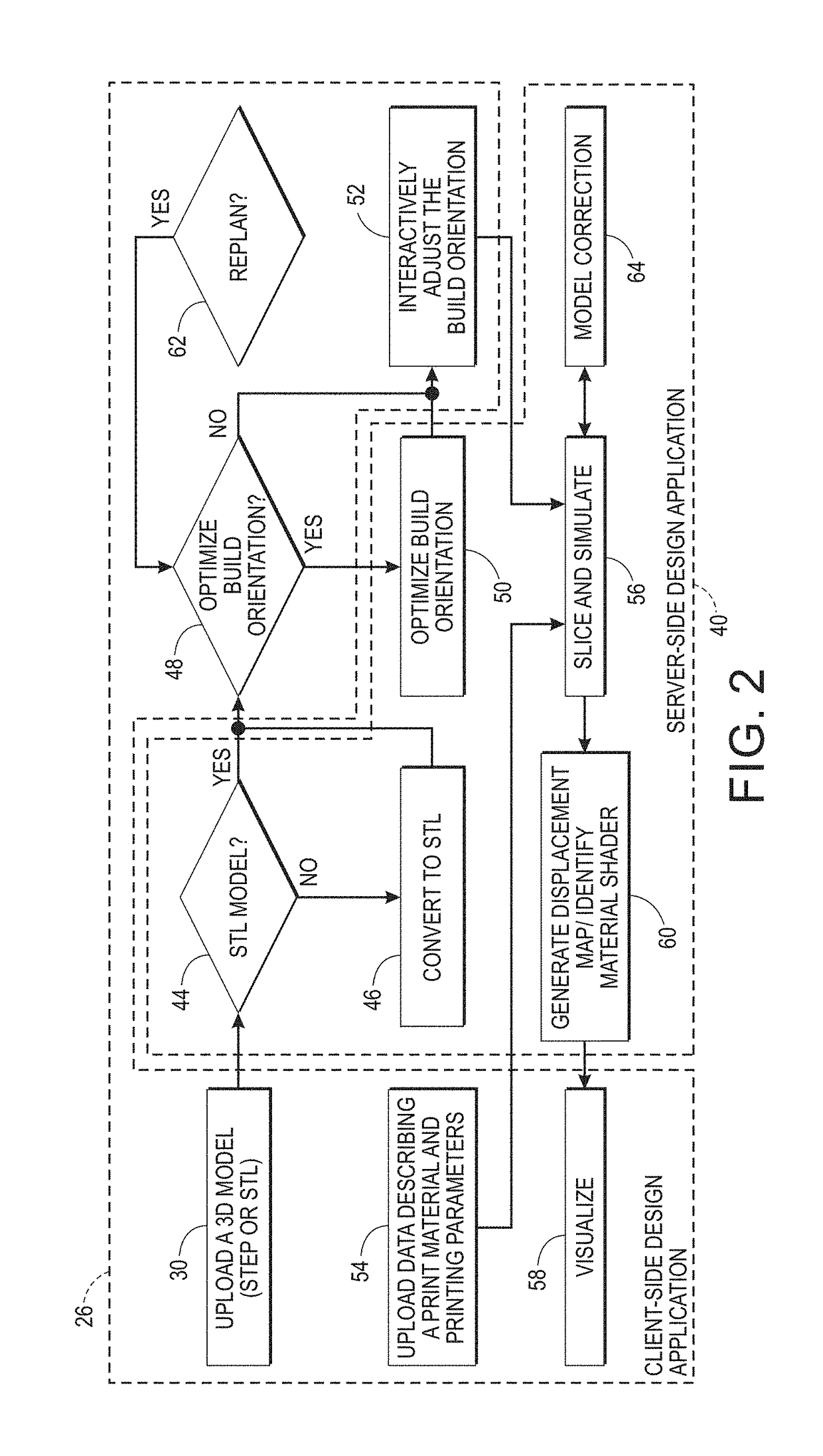
[0051]The present application describes a system to perform design evaluation for three dimensional (3D) printing using manufacturing simulation and to provide feedback prior to printing a 3D solid model. The system evaluates process plans by rapidly analyzing the solid and simulating the layered manufacturing process to identify expected deviations from the intended design. Parameters for the simulation may be tuned based on process and printer specific values. The result of the simulation provides interactive visual feedback that highlights regions that are expected to deviate from design intent, either in appearance or in structural integrity.

[0052]Further, the present application describes a system to perform automated metrology and model correction for 3D printability. Using techniques from mathematical morphology, printability in terms of local size measurements is determined and used to partition the 3D model into regions that can be manufactured up to specified resolutions. ...


PUM


Abstract

A system and a method visualize three dimensional (3D) printability of a 3D model. A 3D printing process of the 3D model is simulated to generate a layered 3D model describing the 3D model as printed. A visual rendering of the layered 3D model is generated, and the visual rendering of the layered 3D model is displayed on a display device.

Description

BACKGROUND[0001]The present application relates generally to design and manufacturing. It finds particular application in conjunction with three dimensional (3D) printing, and will be described with particular reference thereto. However, it is to be appreciated that the present application is also amenable to other like applications.[0002]3D printing, also known as additive or layered manufacturing, is the process of building 3D solid shapes by accumulating material laid out in cross sectional layers. The printing process is driven by the controlled planar translation of a print head in stacked layers that determines the spatial accumulation of material. Depending on the process, the print head typically either deposits material (e.g., in fused deposition modeling (FDM)), cures powder by applying a focused laser (e.g., in selective laser sintering (SLS) and stereolithography (SLA)), sprays liquid binding onto particles (e.g., in inkjet printing), or applies some combination of these...

Claims


Application Information

Patent Timeline
Patent Type & Authority Patents(United States)
IPC IPC(8): G06F17/00G06T19/00G06T17/00G06F17/50
CPCG06F17/5009G06T19/00G06T17/00G06T2219/008G06F30/20
Inventor KIM, WALTERKURTOGLU, TOLGANELATURI, SAIGOPALRANGARAJAN, ARVIND
Owner XEROX CORP
Learn More