
Shoulder bed effects removal

a technology of shoulder bed and effect removal, applied in the field of interpretation of data, can solve problems such as significant effects

Active Publication Date: 2009-10-06
SCHLUMBERGER TECH CORP
View PDF9 Cites 7 Cited by
  • Summary
  • Abstract
  • Description
  • Claims
  • Application Information

AI Technical Summary

Benefits of technology

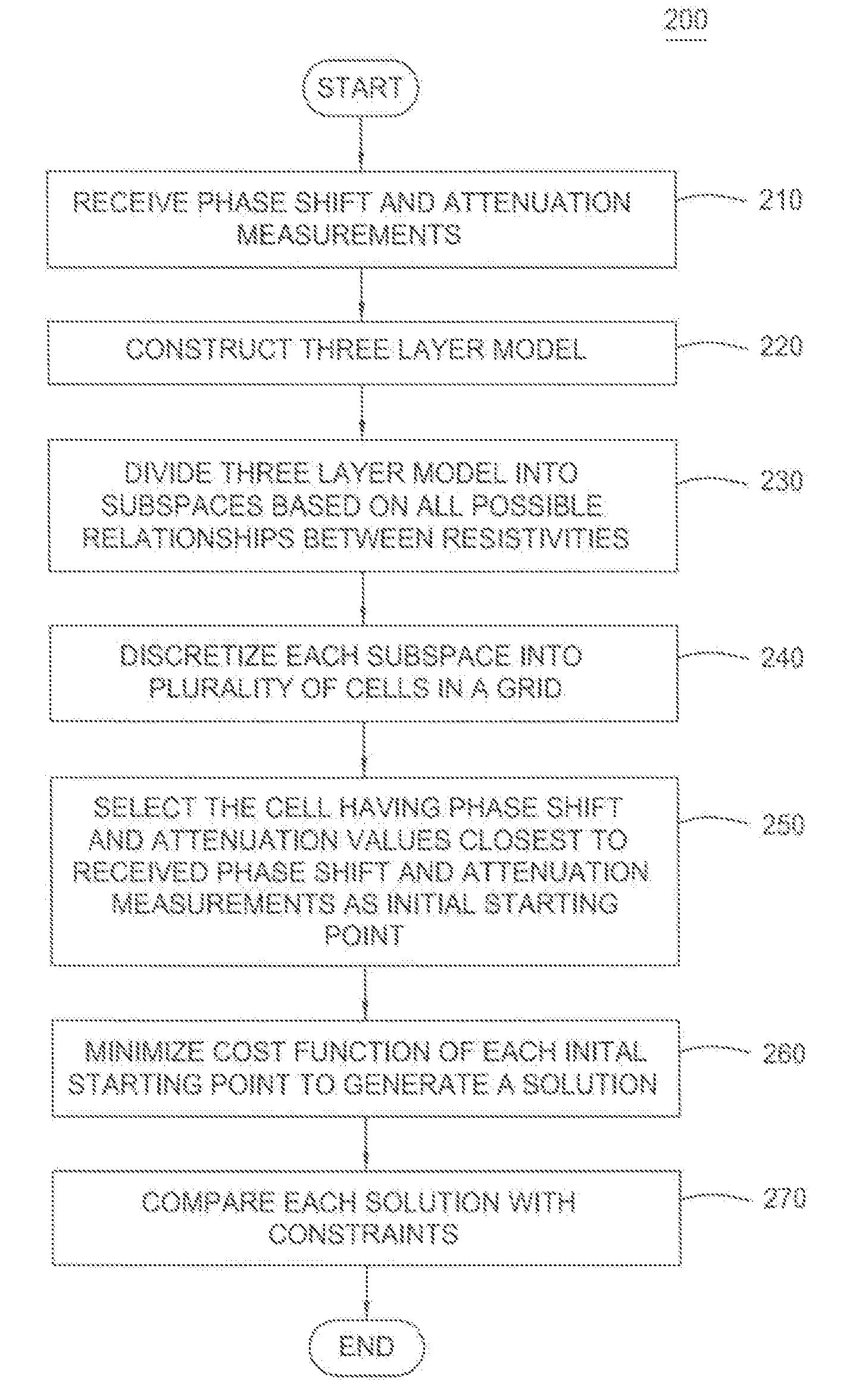
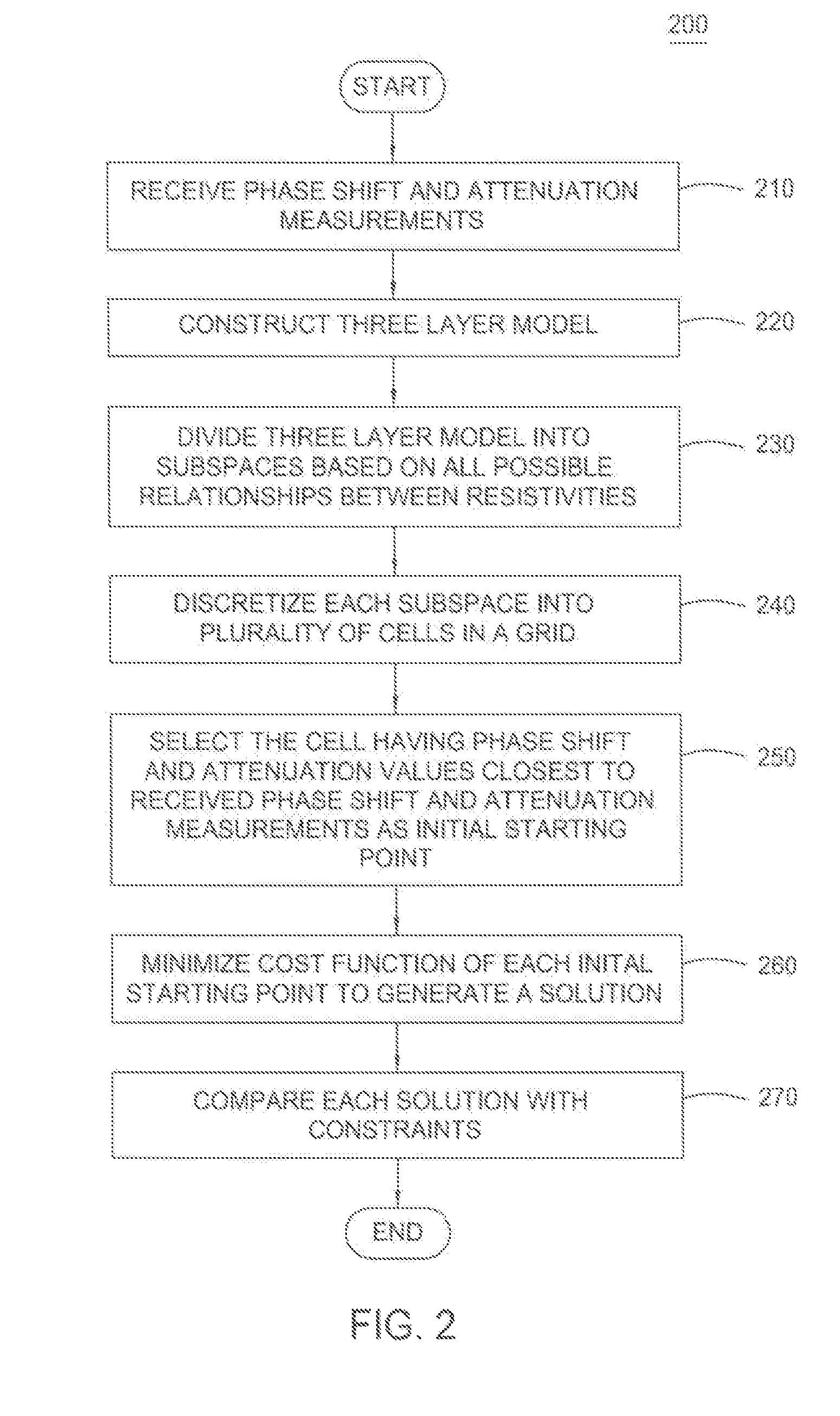
The patent describes different methods for removing shoulder-bed effects from measurements of an earth formation in a wellbore. These methods involve creating a layered model of the formation with parameters that define a parameter space for each layer. The parameter space is then divided into subspaces based on the relationships among the parameters. Candidate solutions are generated by selecting from these subspaces and a final solution is selected based on a cost function. The claimed subject matter is not limited to solving any specific problem and can include any method for removing shoulder-bed effects from wellbore measurements.

Problems solved by technology

Some resistivity tools, such as induction and propagation tools, can sense beds located tens of feet from the measure point and can be significantly affected by shoulder beds, even when the reservoir is thick.

Method used


Image

  • Shoulder bed effects removal
  • Shoulder bed effects removal
  • Shoulder bed effects removal

Examples


Embodiment Construction

[0024]As used here, the terms “up” and “down”; “upper” and “lower”; “upwardly” and downwardly”; “below” and “above”; and other similar terms indicating relative positions above or below a given point or element may be used in connection with some implementations of various technologies described herein. However, when applied to equipment and methods for use in wells that are deviated or horizontal, or when applied to equipment and methods that when arranged in a well are in a deviated or horizontal orientation, such terms may refer to a left to right, right to left, or other relationships as appropriate.

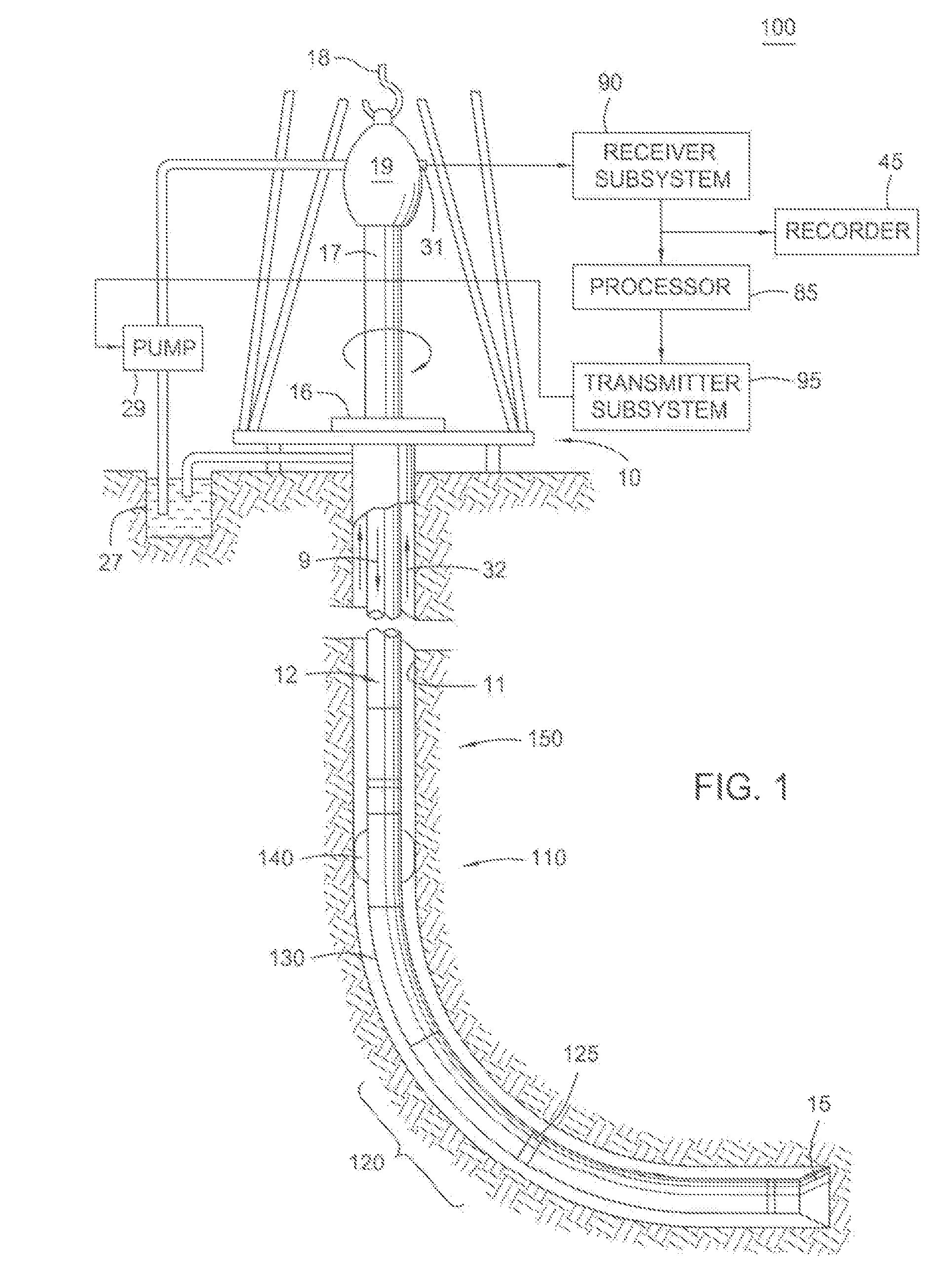
[0025]Implementations of various technologies described herein are directed to removal of shoulder-bed effects from earth formation measurements. FIG. 1 illustrates a drilling environment 100 that may be used in connection with various implementations of those technologies. In one implementation, the drilling environment 100 may include a drilling rig 10 positioned over a wellbore 11...


PUM


Abstract

Various technologies for removing shoulder-bed effects from measurements of an earth formation made in a wellbore. In one implementation, a methodology for removing the shoulder-bed effects includes receiving the measurements and constructing a layered model of the earth formation. Each layer has a set of parameters corresponding to one or more types of the received measurements ascribed to each layer such that the set of parameters define a parameter space for the layered model. The methodology may further include dividing the parameter space into subspaces based on relationships among the parameters, selecting from the subspaces one or more starting points, minimizing a cost function using the one or more starting points to generate one or more candidate solutions having the shoulder-bed effects removed and selecting a final solution from the one or more candidate solutions.

Description

[0001]This application claims the benefit of the filing date of U.S. Provisional Patent Application No. 60 / 672,302 filed Apr. 18, 2005, the disclosure of which is incorporated herein by reference.BACKGROUND[0002]1. Field of the Invention[0003]Implementations of various technologies described herein generally relate to interpreting data obtained with well logging tools.[0004]2. Description of the Related Art[0005]The following descriptions and examples are not admitted to be prior art by virtue of their inclusion within this section.[0006]Determining the porosity and fluid content of subsurface earth formations are critical elements in maximizing the efficiency of oil, gas, and water (“formation fluids”) exploration. In order to improve formation fluids exploration, drilling, and production operations, it may be necessary to gather as much information as possible on the properties of the underground earth formations as well as the environment in which drilling takes place.[0007]The c...

Claims


Application Information

Patent Timeline
Patent Type & Authority Patents(United States)
IPC IPC(8): G06G7/48G01V3/18G01V3/00E21B47/00G01V3/38
CPCG01V3/24G01V1/48G01V3/38G01V5/04G01V3/30G01V11/00
Inventor YANG, JIANOMERAGIC, DZEVATLIU, CHENGBINGLI, QIMINGSMITS, JAN W.ZENG, YANQINGCLIMENT, HELENE C.
Owner SCHLUMBERGER TECH CORP
Learn More