
Male connector

a technology of male connectors and connectors, applied in the direction of connection, electrical apparatus, coupling device connection, etc., can solve the problems of increasing the rate, dramatic decrease of the rise time in the server storing industry, and increasing the clock frequency, so as to reduce the crosstalk, eliminate the crosstalk, and effect of effective electromagnetic shielding function

Active Publication Date: 2018-04-10
AMPHENOL EAST ASIA ELECTRONICS TECH SHENZHEN
View PDF14 Cites 13 Cited by
  • Summary
  • Abstract
  • Description
  • Claims
  • Application Information

AI Technical Summary

Benefits of technology

The present patent is about improving the male connector by adding a conductive shield to reduce crosstalk between terminals. The conductive shield is located between the set of terminals and eliminates interference when they transmit signals simultaneously. Ground terminals are also connected via conductive plastic to further reduce crosstalk. This results in better signal quality and improved performance.

Problems solved by technology

As the data storing capacity continues to rise, the demand for higher transmission rate has been on the increase, which means the increase of clock frequency and dramatic decrease of the rise time in the server storing industry.

Method used


Image

  • Male connector
  • Male connector
  • Male connector

Examples


embodiment 1

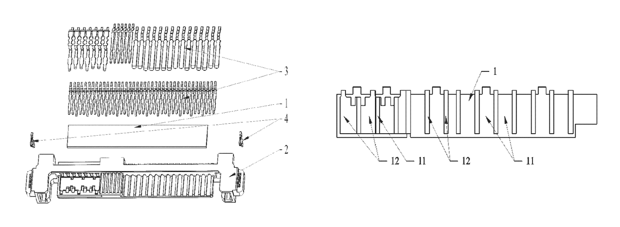
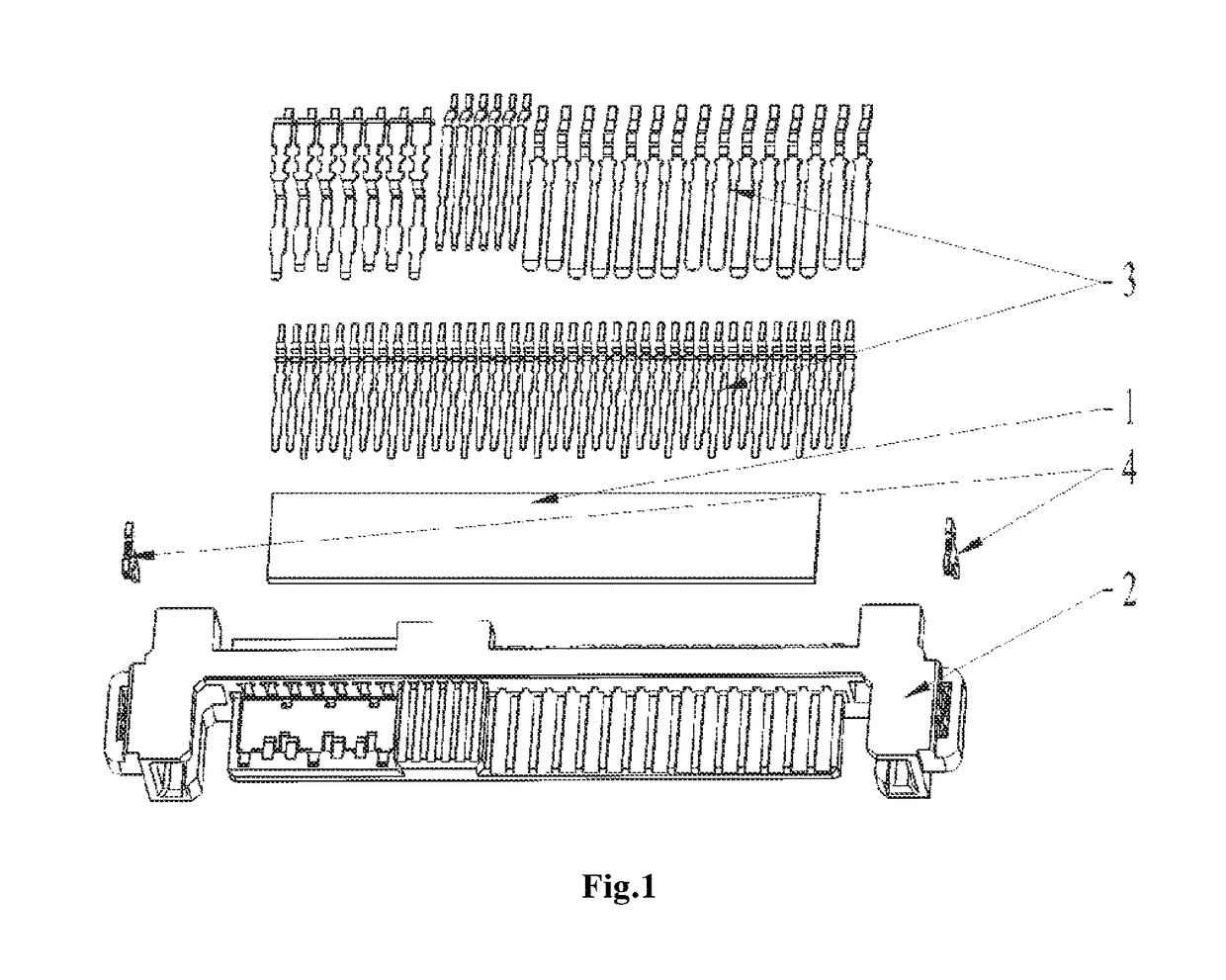
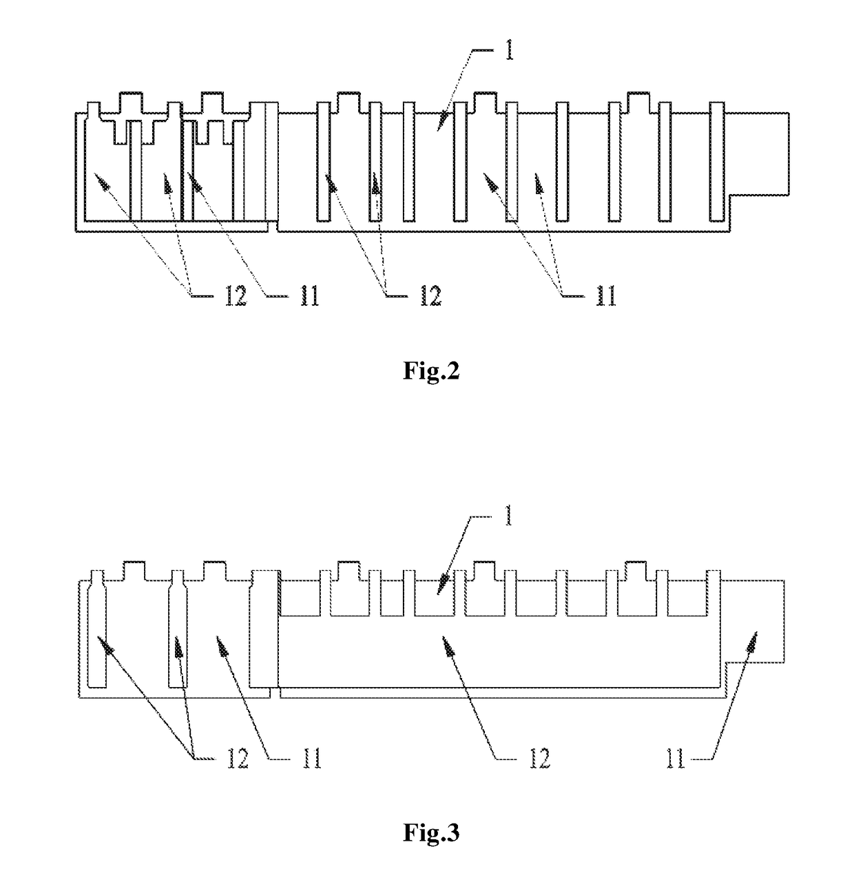
[0013]A new male connector comprises a conductive shielding 1, a connector body 2, a set of terminals 3, and two fixing tabs 4.

[0014]The connector body 2 is provided with a cavity within which the set of terminals 3 can be accommodated and is made from plastic cement. The set of terminals 3 are located within the cavity of the connector body 2. The conductive shielding 1 can be inserted between the connector body 2 and the set of terminals 3, and specifically includes several shielding bars 11 and conductive areas 12. The bar shaped shielding bars 11 are made from metal, and the conductive areas 12, which are embedded in the shielding bars 11 and connected with the ends of the set of terminals 3, are made from conductive plastic cement.

[0015]The fixing tabs 4 are respectively located at the two sides of the connector body 2.

[0016]In light of general technical knowledge, the present technical solutions can be achieved by other embodiments which do not depart from the spiritual substa...


PUM


Abstract

A new connector with effective shielding function. The new connector includes conductive shielding, a connector body and a set of terminals. The connector body is provided with a cavity within which the set of terminals can be accommodated and is made from plastic cement; the set of terminals are located within the cavity of the connector body. The conductive shielding can be inserted between the connector body and the set of terminals, and specifically includes several shielding bars and conductive areas; the shielding bars are made from metal, and the conductive areas, which are embedded in the shielding bars and connected with the ends of the set of terminals, are made from conductive plastic cement.

Description

TECHNICAL FIELD[0001]The present application relates to a male connector, particularly to a new connector with effective shielding function.BACKGROUND[0002]As the data storing capacity continues to rise, the demand for higher transmission rate has been on the increase, which means the increase of clock frequency and dramatic decrease of the rise time in the server storing industry. The SAS and PCIe channels of most current connectors will be subject to crosstalk during communication when used simultaneously, which should be avoided.SUMMARY OF THE APPLICATION[0003]To resolve the above described technical problems, the present application provides a connector with effective electromagnetic shielding function.[0004]To achieve the above described objective, the technical solutions of the application are detailed as follows: a new male connector comprises a conductive shielding, a connector body and a set of terminals.[0005]The connector body, which is made from plastic cement, is provid...

Claims


Application Information

Patent Timeline
Patent Type & Authority Patents(United States)
IPC IPC(8): H01R13/6585H01R13/6599H01R13/631
CPCH01R13/6585H01R13/631H01R12/725H01R13/6599
Inventor JIANG, FUANWANG, XIANGLIAO, LEI
Owner AMPHENOL EAST ASIA ELECTRONICS TECH SHENZHEN
Learn More