
Method and system for determining the concentration of an analyte in a fluid sample

a fluid sample and analyte technology, applied in the field of improved methods for detecting the presence or quantity of analyte in fluid sample, can solve the problems of interference with the analytical procedure, non-analyte species can be particularly problematic, and contaminants are evidently present in biological samples undergoing analysis, so as to achieve accurate determination of the concentration of analyte

Active Publication Date: 2018-04-10
LABCYTE
View PDF5 Cites 1 Cited by
  • Summary
  • Abstract
  • Description
  • Claims
  • Application Information

AI Technical Summary

Benefits of technology

[0018]Accordingly, the present invention addresses the aforementioned need in the art by providing an improved method for accurately determining the concentration of an analyte in a fluid sample.
[0019]In one embodiment, an improved method is provided for determining the concentration of an analyte in a fluid sample that also contains a necessary non-analyte component, where the method comprises volatilizing and ionizing the fluid sample, and introducing the ionized, volatilized sample into an ionic analyte detection device that provides an analyte signal proportional in intensity to the quantity of analyte detected, e.g., a mass spectrometer, wherein the improvement comprises replacing the necessary non-analyte original component with a substitute component that (a) functions as the necessary non-analyte component in the fluid sample, i.e., serves the same purpose with respect to the fluid sample, (b) is more volatile than the original component and / or the analyte, and / or undergoes a chemical reaction to yield at least one reaction product that is more volatile than the original component and / or the analyte, and (c) results in an increase in the intensity of the analyte signal and / or a greater signal to noise ratio than either the signal intensity or signal to noise ratio obtained using the original component.
[0020]In another embodiment, acoustic ejection is used to generate nanoliter-sized droplets that are then volatilized, ionized, and analyzed, wherein “nanoliter-sized” droplets are defined herein as droplets of 5 nl or less. In acoustic ejection, an acoustic ejector directs focused acoustic energy into a reservoir containing the fluid sample in a manner that results in the ejection of fluid droplets from the surface of the fluid sample. Acoustic ejection provides many advantages over other droplet generation methodologies; for instance, acoustic fluid ejection devices are not subject to clogging, misdirected fluid or improperly sized droplets, and acoustic technology does not require the use of tubing or any invasive mechanical action. Acoustic ejection technology as described, for example, in U.S. Pat. No. 6,802,593 to Ellson et al., enables rapid sample processing and generation of droplets in the nanoliter or even picoliter range. In addition, acoustic ejection enables control over droplet size as well as repeated generation of consistently sized droplets. See U.S. Pat. No. 6,416,164 B1 to Stearns et al., incorporated by reference herein. As explained in that patent, the size of acoustically ejected droplets from a fluid surface can be carefully controlled by varying the acoustic power, the acoustic frequency, the toneburst duration, and / or the F-number of the focusing lens.

Problems solved by technology

The presence of contaminants in biological samples undergoing analysis is obviously problematic for a number of reasons.
Contaminants might cause interference with the analytical procedure, chemically or physically altering the sample or the analyte itself.
The same problem can be caused by necessary components of the fluid sample, such as buffer salts, surfactants, and other species that may be essential for biochemical steps preceding the analysis.
The presence of non-analyte species can be particularly problematic in mass spectrometry, where analyte concentration may be very low and the number and concentration of contaminants and interfering components may be relatively high.
When these species reduce detection sensitivity by decreasing the signal-to-noise ratio and give rise to a flawed analysis, the problem has been characterized as “ion suppression.” See Weaver et al.
Weaver et al. cites several possible mechanisms underlying ion suppression: (1) competition for charge between analyte and ion-suppressing agent, leading to reduced ionization of analyte; (2) large concentrations of ion-suppressing agents causing an increase in surface tension as well as an increase in droplet viscosity, in turn resulting in decreased evaporation efficiency; and (3) gas phase reactions between the ionized analyte and other species in the sample, resulting in an overall loss of charge from the analyte ions.
As noted above, high concentrations of interfering components give rise to increased surface tension and viscosity that in turn reduce evaporation efficiency, and this is known to have a marked effect on ionization efficiency.
It should also be pointed out that the degree of ion suppression may be dependent on the concentration of the analyte being monitored, and with the ever-increasing demand to lower detection threshold, ion suppression may become a more and more serious problem.
These processes require time, materials, and equipment, and can reduce the available quantity of an already small sample.

Method used


Image

  • Method and system for determining the concentration of an analyte in a fluid sample
  • Method and system for determining the concentration of an analyte in a fluid sample
  • Method and system for determining the concentration of an analyte in a fluid sample

Examples


example 1

[0164]In this example, the impact of buffer volatility on the mass spectrometric determination of caffeine was evaluated using ammonium acetate as a volatile buffer salt and sodium chloride as a nonvolatile buffer salt. Fluid samples were prepared with varying concentrations of either ammonium acetate or sodium chloride, at 1 mM, 2 mM, 5 mM, 10 mM, 25 mM, 50 mM, 100 mM, 250 mM, and 500 mM. Sample droplets were generated using a modified Echo® 555 liquid handler (Labcyte Inc., Sunnyvale, Calif.). The instrument was modified to move the transducer assembly to the exterior of the instrument underneath a nozzle to allow the droplet stream to be exposed to 195° C. heat, thus enabling gas phase extraction of volatile salt, and pulled into a beta version of the SQ Detector II mass spectrometer (Waters Micromass).

[0165]FIG. 1 is a plot of normalized signal at m / z=195 versus ammonium acetate (♦) or sodium chloride (▪) concentration (mM). As may be seen, the concentration of caffeine detected...

example 2

[0167]This example describes an additional evaluation of the impact of buffer volatility on the mass spectrometric determination of caffeine, with magnesium acetate used as a volatile buffer salt and magnesium chloride as a nonvolatile buffer salt. The signal intensity of caffeine and its sodium adduct was evaluated in four concentrations of six salt systems. The data, plotted in FIG. 2, shows that standard ESI system sensitivity is heavily impacted by non-volatile salts and less impacted by a volatile salt, at similar concentrations. That is, the uppermost data points in the plot correspond to the signal obtained with fluid samples containing caffeine and ammonium acetate as a buffer salt. The experiment may be repeated to carry out mass spectrometric determinations of other analytes with substantially the same results.

example 3

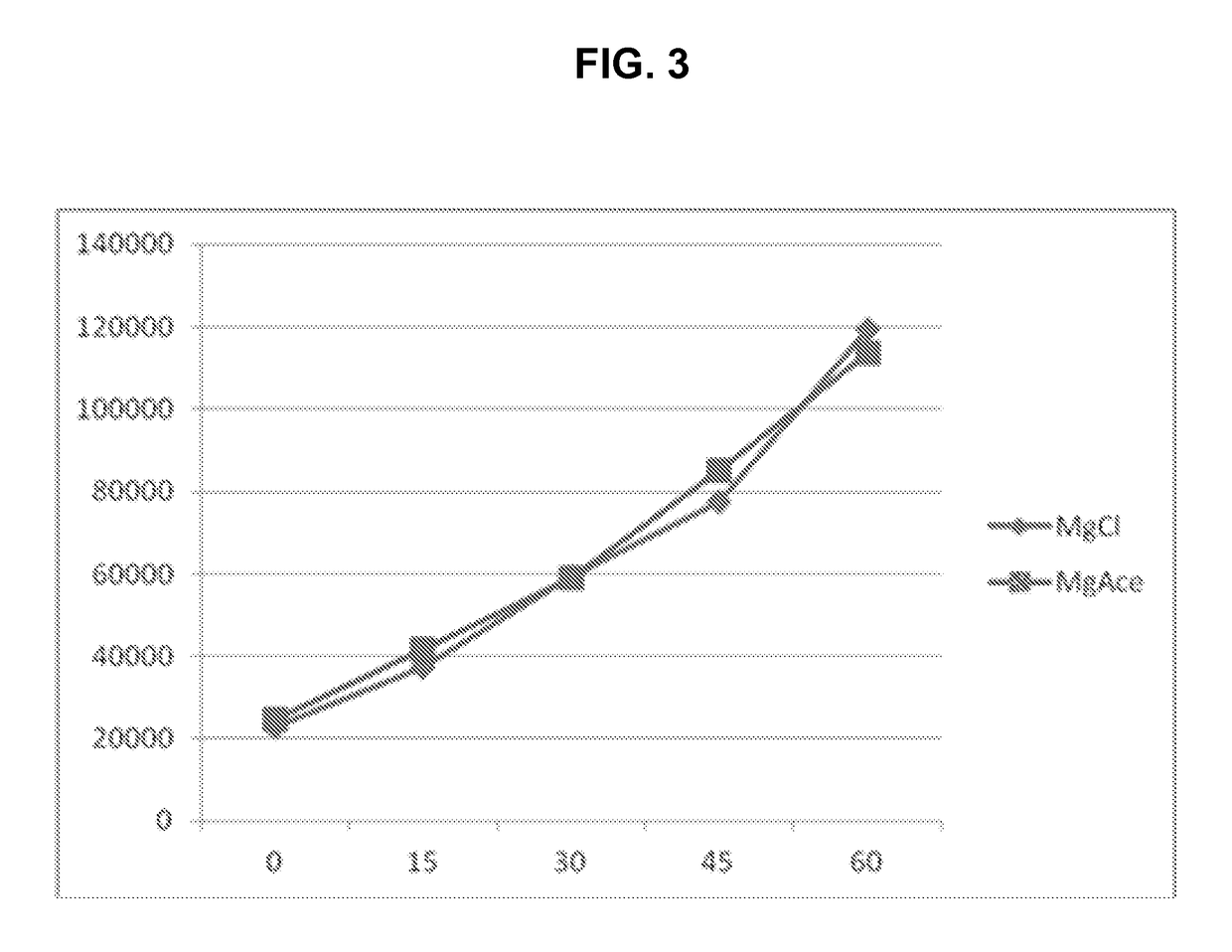
[0168]In this example, a kinase assay was conducted in which magnesium is required by the enzyme used, and the assay measures the increase in concentration of a phosphorylated peptide substrate with time. One set of samples was formulated with magnesium chloride, a relatively nonvolatile compound, and a second set of samples was formulated with magnesium acetate, a more volatile compound. The assay results using each type of magnesium salt are illustrated in FIG. 3, in which time, in minutes, is represented on the X-axis, and luminescence is represented on the Y-axis. The graph comparing results obtained for the assay employing magnesium chloride (♦) with those obtained for the assay employing magnesium acetate (▪) show that the assay was not hindered or biased by the source of magnesium ions.

[0169]In many assay systems, certain non-volatile and / or highly electronegative buffer components are used; however, these components are not unique creating the biological or chemical outcome ...


PUM

PropertyMeasurementUnit
flow rateaaaaaaaaaa
temperatureaaaaaaaaaa

Abstract

A method and system are provided for detecting the concentration of an analyte in a fluid sample. The method and system involve analysis of a volatilized, ionized fluid sample using a mass spectrometer or other ionic analyte detection device that provides a signal proportional in intensity to the quantity of ionized analyte detected. The improvement involves replacement of a necessary non-analyte component in the fluid sample with a substitute component that serves the same purpose as the original component but is either more volatile than the original component and / or the analyte or undergoes a reaction to provide lower molecular weight reaction products, and results in an increased intensity in signal and signal-to-noise ratio. Acoustic fluid ejection is a preferred method of generating nanoliter-sized droplets of fluid sample that are then volatilized, ionized, and analyzed. Also provided are zwitterionic compounds suitable as the substitute components that when ionized and heated decompose to provide carbonic dioxide, a nitrogenous species such as ammonia, an amine, or nitrogen gas, and a volatile aromatic compound.

Description

CROSS-REFERENCE TO RELATED APPLICATION[0001]This application claims priority under 35 U.S.C. § 119(e)(1) to provisional U.S. Patent Application Ser. No. 62 / 065,600, filed Oct. 17, 2014, the disclosure of which is incorporated by reference herein.TECHNICAL FIELD[0002]The present invention relates generally to improved methods for detecting the presence or quantity of an analyte in a fluid sample, and more particularly relates to improvements in such methods where nanoliter-sized fluid droplets are generated and the sample accurately analyzed. The invention finds utility in the fields of analytical chemistry, biological research, pharmaceuticals, and medicine.BACKGROUND[0003]Accurate determination of the presence, identity, concentration, and / or quantity of an ionized species in a sample is critically important in many fields. Most techniques used in such analyses involve ionization of species in a fluid sample prior to introduction into the analytical equipment employed. The choice o...

Claims


Application Information

Patent Timeline
Patent Type & Authority Patents(United States)
IPC IPC(8): G01N1/28G01N33/68H01J49/04C12Q1/68
CPCG01N1/28H01J49/04H01J49/0431C12Q1/68Y10T436/25875G01N33/6851H01J49/0422Y10T436/24G01N33/6848
Inventor ELLSON, RICHARD N.STEARNS, RICHARD G.OLECHNO, JOSEPH D.SINCLAIR, IANWINGFIELD, JONATHAN
Owner LABCYTE
Learn More