
Composite beam having truss reinforcement embedded in concrete

a technology of concrete and truss reinforcement, applied in the field of composite beams, can solve the problems of long construction period, difficult construction, higher material cost, etc., and achieve the effect of wide operation space, improved construction convenience, and efficient handling of construction load

Active Publication Date: 2018-03-06
KWON YONG KEUN
View PDF22 Cites 1 Cited by
  • Summary
  • Abstract
  • Description
  • Claims
  • Application Information

AI Technical Summary

Benefits of technology

[0020]First, there is an effect that since the fabricated truss acts as the construction member which can efficiently endure the construction load and the concrete weight, the support can be excluded, and since it can secure a wide operation space, the construction convenience can be improved, and since a framework can be first installed without waiting the curing of the concrete, the construction period can be reduced.
[0020]First, there is an effect that since the fabricated truss acts as the construction member which can efficiently endure the construction load and the concrete weight, the support can be excluded, and since it can secure a wide operation space, the construction convenience can be improved, and since a framework can be first installed without waiting the curing of the concrete, the construction period can be reduced.
[0022]Third, the screw rod combining the upper chord, the lower chord and the folding type web member acts as a fore end connection member which makes the concrete and the fabricated truss to act integrally so as to improve the structural performance of the flush type composite beam.
[0023]Fourth, the folding type web member can improve reduce the transportation fee and the deposit fee and the construction convenience by reducing the volume by folding at the stage of transportation and deposit, by expanding and assembling at the time of assembly and installation.
[0024]Fifth, since the upper chord and the upper chord of the flush type fabricated truss composite beam from which the sheathing board is removed after curing of the concrete act as the deflection reinforcing member and the folding type web member acts as the shear reinforcing member, the structural performance is superior and the rigidity against the deflection and the vibration is superior compared to the conventional exposed type composite beam.

Problems solved by technology

Therefore, since the reinforced concrete structure is accompanied with additional processes such as removal of a form, removal of the support or the like, there is a disadvantage that the construction is difficult and the construction period is lengthened.
A steel structure does not require a separate erection work at the time of construction, however, has problems that the material cost is higher than the reinforced concrete structure and the steel member is exposed so that the durability and the refractory property are deteriorated.
The steel plate fabricated composite beam suggested by this patent has an advantage that since there is no protrusion to the side of the web plate by combining the web plate to the side surface of the lower flange, the portion of the structure itself where the dust is accumulated can be removed, however, since the steel plate unit manufactured in U form so as to function as a permanent form is usually composed of a thin plate of which the thickness of the steel plate is about 6 mm, there is a disadvantage that the section rigidity is very small, so that when filling the concrete inside of the steel unit and when assembling the reinforcing bar to a floor plate and pouring the concrete thereto, it is difficult to support the construction load, therefore, since the construction is carried out by placing supports at intermediate places of the steel plate unit at the construction stage, it is difficult to anticipate the site construction operability and the construction period saving, and the steel unit which is exposed to the outside is very weak to the fire.

Method used


Image

  • Composite beam having truss reinforcement embedded in concrete
  • Composite beam having truss reinforcement embedded in concrete
  • Composite beam having truss reinforcement embedded in concrete

Examples


Embodiment Construction

[0033]Although the present invention will be described in detail below with reference to the accompanying drawings, the suggested embodiments are only for exemplification of the present invention for the definite understanding of the present invention and the present invention is not limited to them.

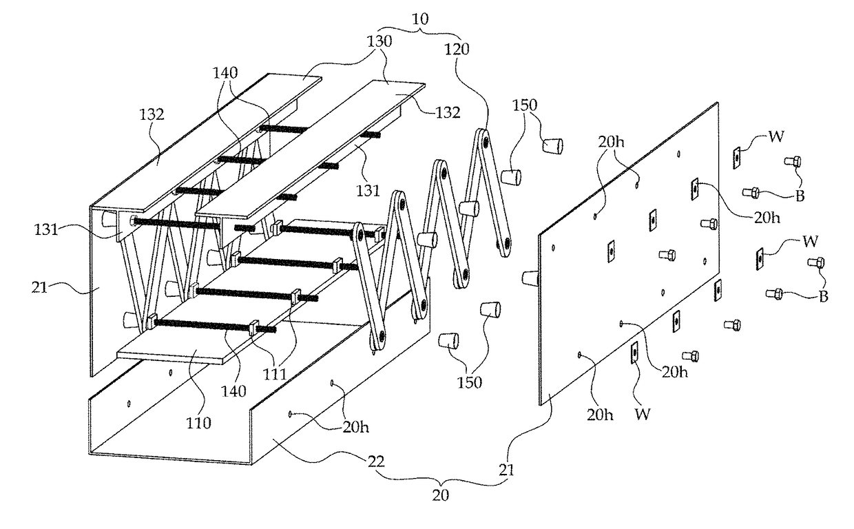
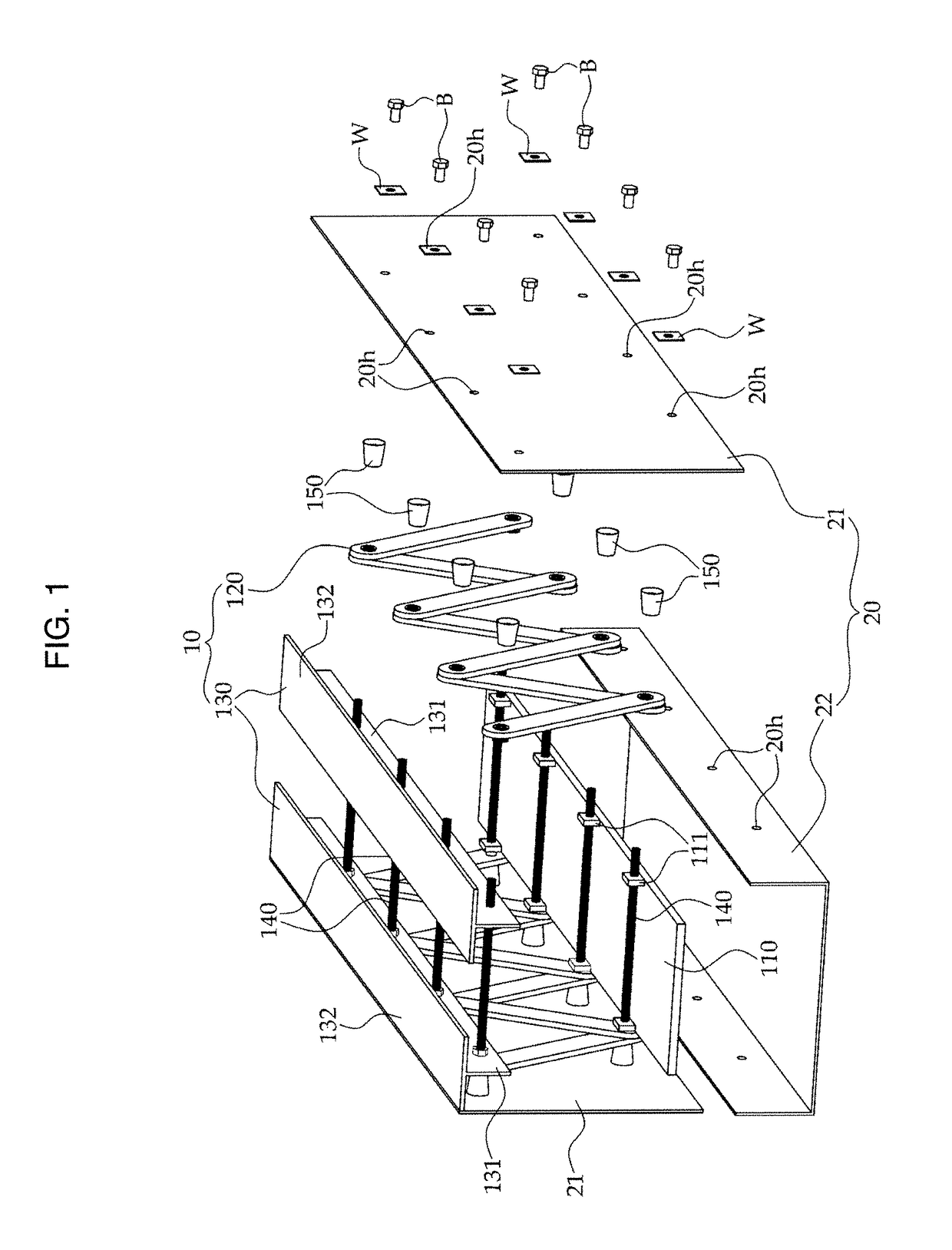
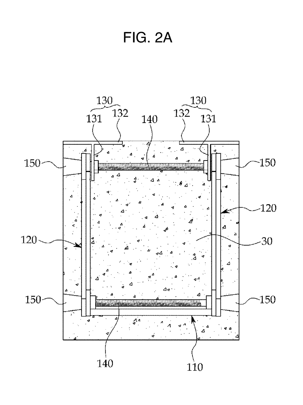
[0034]FIG. 1 is an exploded perspective view of a flush type fabricated truss composite beam attached with a sheathing board according to an embodiment of the present invention and FIG. 2 is a sectional view.

[0035]The flush type fabricated truss composite beam attached with the sheathing board according to the present invention largely comprises a fabricated truss 10, a sheathing board 20, and a concrete 30.

[0036]The fabricated truss 10 is consisted of a truss member consisting of a lower chord, a web member and an upper chord, and the lower chord 110 of the fabricated truss 10 according to the present invention is consisted in a plate shape of a predetermined thickness, and to the lower...


PUM


Abstract

The present invention relates to a composite beam in which a fabricated truss is embedded in the concrete, and more particularly, it relates to a composite beam in which the fabricated truss acts as a truss beam which endures the concrete weight and the construction load in the liquid phase before the curing of the concrete and acts as a main structural member together with the concrete after the curing of the concrete.

Description

CROSS-REFERENCE TO RELATED APPLICATIONS[0001]This application is a 371 of PCT / KR2016 / 000899 filed Jan. 27, 2016, which claims the benefit of foreign priority of Korean Patent Application No. 10-2015-0023632 filed Feb. 16, 2015, the subject matter of which is hereby incorporated by reference in its entirety.BACKGROUND(a) Technical Field[0002]The present invention relates to a composite beam in which a fabricated truss is embedded in the concrete, and more particularly, it relates to a composite beam in which the fabricated truss acts as a truss beam which endures the concrete weight and the construction load in the liquid phase before the curing of the concrete and acts as a main structural member together with the concrete after the curing of the concrete.(b) Background Art[0003]Reinforced concrete structure requires a sheathing board to maintain a shape of the concrete of the liquid phase during the curing period of the concrete and requires a catgut, yoke and support for controlli...

Claims


Application Information

Patent Timeline
Patent Type & Authority Patents(United States)
IPC IPC(8): E04B5/40E04C5/065E04C3/20E04C3/293E04C3/29E04B1/41E04B1/24E01D101/26
CPCE04B5/40E04C3/205E04C3/291E04C3/293E04C5/065E04B2001/4192E01D2101/262E04B2001/2448E04B2001/2457E04C3/005
Inventor KWON, YONG KEUN
Owner KWON YONG KEUN
Learn More