
Airbag apparatus

a technology of airbags and occupants, applied in the direction of pedestrian/occupant safety arrangements, vehicular safety arrangments, vehicle components, etc., can solve the problems of airbags that cannot adequately restrain the occupants on a case-by-case basis, and airbags that cannot adequately protect the occupants

Active Publication Date: 2018-02-27
MAZDA MOTOR CORP
View PDF15 Cites 10 Cited by
  • Summary
  • Abstract
  • Description
  • Claims
  • Application Information

AI Technical Summary

Benefits of technology

The airbag apparatus effectively inhibits the inclination and displacement of the first airbag, allowing for adequate protection of the head region by providing a larger surface area for impact absorption, thereby enhancing occupant safety during oblique collisions.

Problems solved by technology

However, the airbag apparatus disclosed in the Patent Literature 1 is likely to fail to adequately receive (sufficiently restrain) an occupant on a case-by-case basis.
Once such a deformation occurs, the occupant's head region is more likely to be displaced laterally along the rear surface of the front airbag (i.e., displaced from a central region to a peripheral edge region of the front airbag), leading to a risk that the front airbag becomes unable to receive the occupant's head region with a sufficient force, resulting in failing to achieve adequate protection of the occupant.
In other word, if the drive timing is deviated even just slightly, it becomes impossible to realize an intended bilaterally asymmetric configuration.
Moreover, the lateral portion of the airbag closer to the opponent object needs to be largely inflated rearwardly, and accordingly an internal volume of the airbag is increased, so that a time required for deployment becomes longer, leading to a risk of becoming unable to adequately protect an occupant.

Method used


Image

  • Airbag apparatus
  • Airbag apparatus
  • Airbag apparatus

Examples


Embodiment Construction

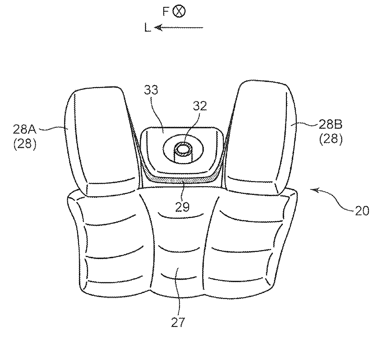
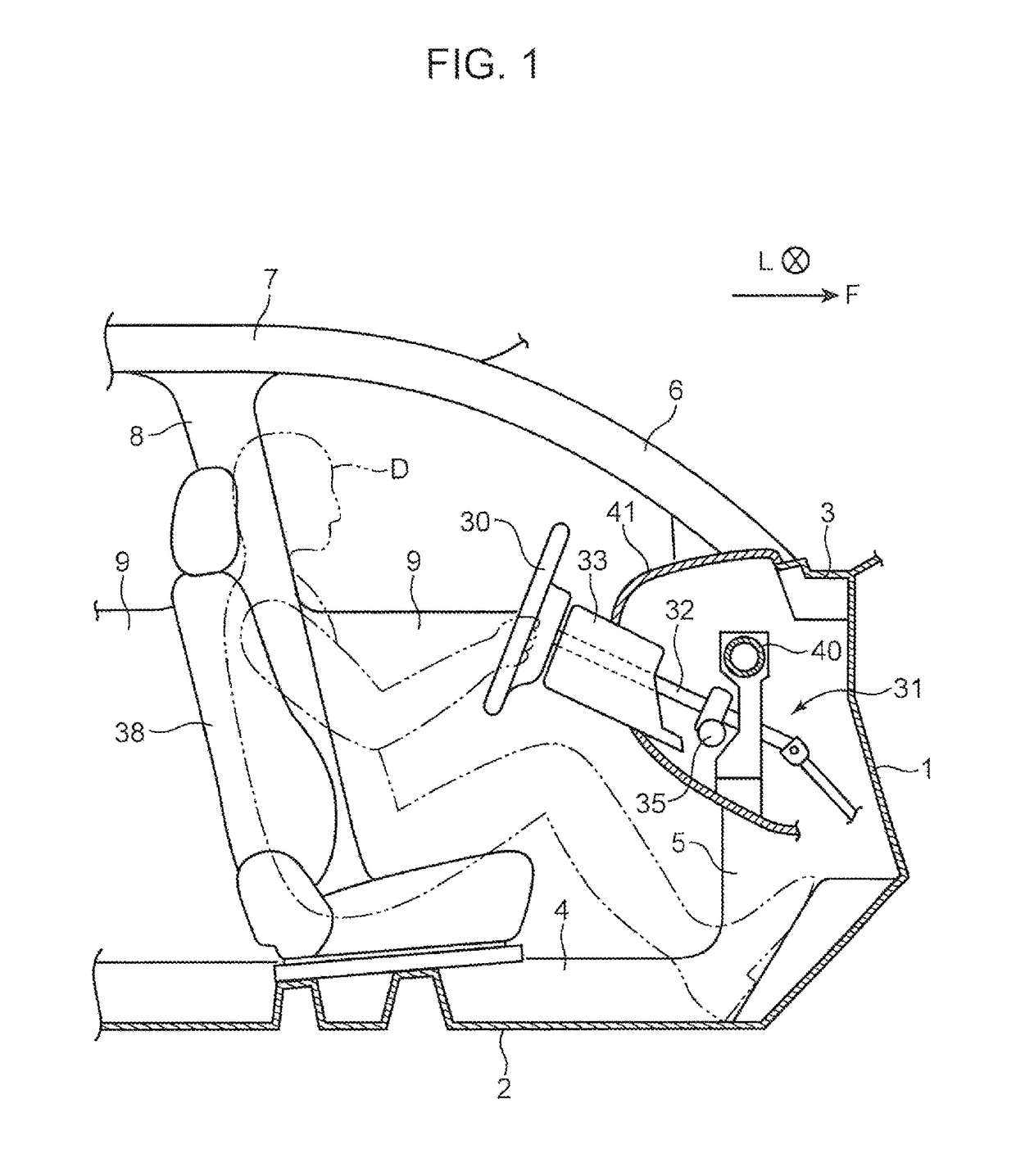
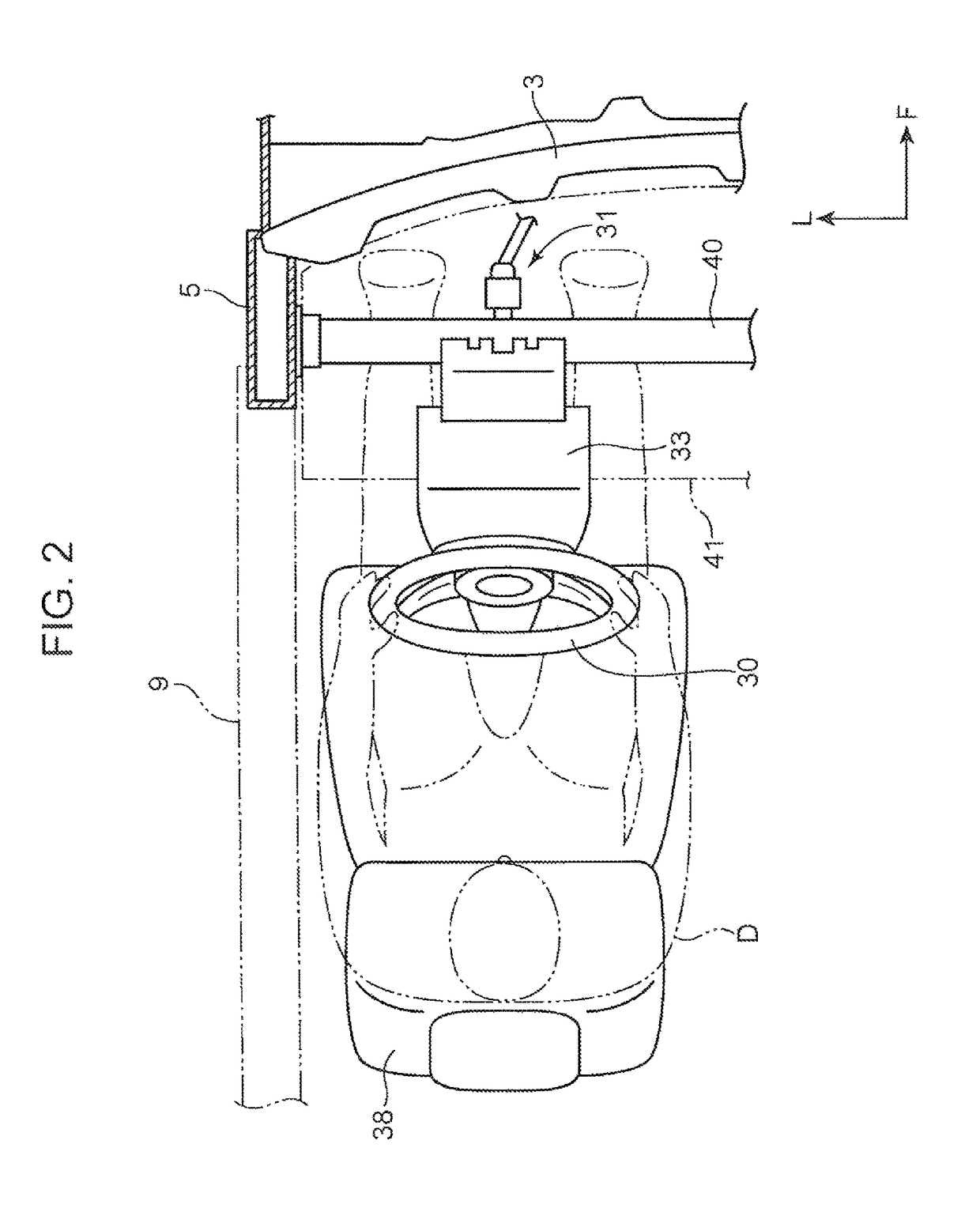
[0021]FIGS. 1 and 2 depict an internal structure of a passenger compartment of a vehicle using an airbag apparatus according to one embodiment of the present invention. It should be noted that, although the side view of FIG. 1 depicts only a left side wall of the passenger compartment, a right side wall of the passenger compartment has a similar structure. In FIGS. 1 and 2, the arrow F indicates a forward direction of the vehicle, and the arrow L indicates a leftward direction of the vehicle (In other words, a side opposite to the arrow F is a rearward direction, and a side opposite to the arrow L is a rightward direction). The same applies to the aftermentioned figures.

[0022]As mainly depicted in FIG. 1, the vehicle in this embodiment comprises; a dash panel 1 partitioning between an engine compartment and the passenger compartment; a floor panel 2 extending rearwardly from a lower edge of the dash panel 1; a cowl panel 3 provided along an upper edge of the dash panel 1; a pair of ...


PUM


Abstract

Disclosed is an airbag apparatus which comprises: a first airbag configured to be deployed rearwardly from a steering wheel during an oblique collision of a vehicle; and a second airbag configured to be deployed rearwardly and upwardly from a position below a steering shaft during the oblique collision of the vehicle. The second airbag comprises an upward deployment portion capable of, in its deployed state, extending upwardly via a lateral side of the steering shaft, wherein the upward deployment portion is disposed between a lateral portion of the first airbag in its deployed state and an instrument panel.

Description

TECHNICAL FIELD[0001]The present invention relates to an airbag apparatus for protecting an occupant upon an oblique collision of a vehicle.BACKGROUND ART[0002]In the event of an oblique collision accident in which an opponent object collides with an own vehicle obliquely from a front end of the vehicle, an occupant is pushed and moved obliquely forwardly from his / her initial position (seated position). With a view to protecting an occupant in the event of such an oblique collision accident, there has heretofore been employed a technique of deploying airbags from both front and lateral sides of the occupant.[0003]For example, a vehicle disclosed in JP 2013-133049A (hereinafter referred to as “Patent Literature 1”) is equipped with a front airbag configured to be deployed rearwardly from an instrument panel disposed at a front end of a passenger compartment, and a side airbag configured to be deployed downwardly from a lateral edge portion (a pillar or a roof side rail) of an upper w...

Claims


Application Information

Patent Timeline
Patent Type & Authority Patents(United States)
IPC IPC(8): B60R21/206B60R21/231B60R21/2338B60R21/203B60R21/233B60R21/00B60R21/16
CPCB60R21/203B60R21/206B60R21/231B60R21/233B60R21/2338B60R2021/23386B60R2021/0051B60R2021/161B60R2021/23107B60R2021/23169B60R2021/23308B60R2021/0009
Inventor TAKESHITA, HIROAKINAGATANI, TAKASHIHIRATA, MOTOHARUYAMANISHI, MITSUTOSHISATO, MOTOHARU
Owner MAZDA MOTOR CORP
Learn More