Vehicle seat
a seat and vehicle technology, applied in the field of seats, can solve the problems of insufficient space around the seat, difficult to add such various systems as described above to the vehicle seat, etc., and achieve the effect of simplifying the system configuration
- Summary
- Abstract
- Description
- Claims
- Application Information
AI Technical Summary
Benefits of technology
Problems solved by technology
Method used
Image
Examples
first embodiment
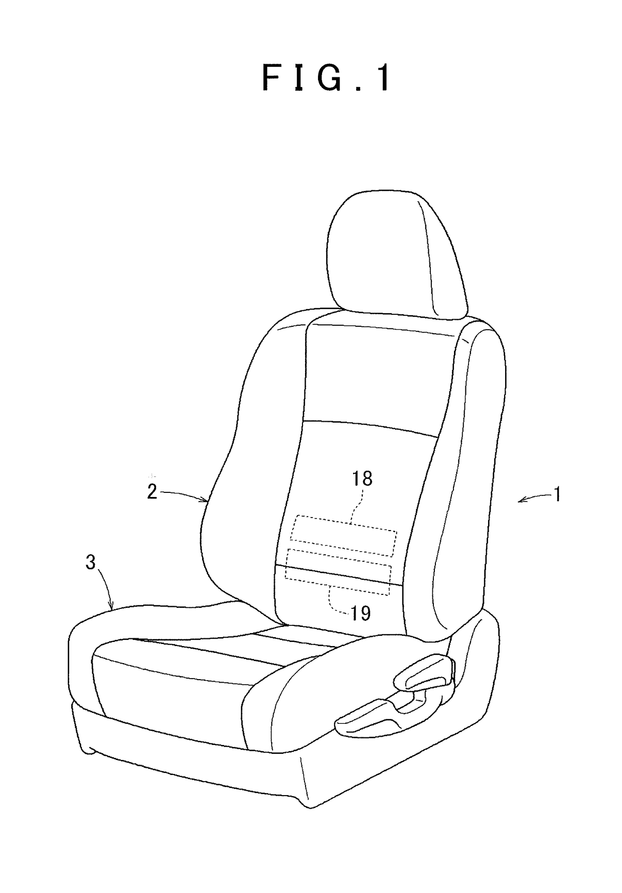
[0042]FIG. 1 shows the present invention. This embodiment shows an example where a lumbar support in which a bladder is used is applied to a seat 1 for a vehicle (hereinafter simply referred to as the seat). The seat 1 includes a seat cushion 3 constituting a seat part and a seat back 2 constituting a backrest, and a lumbar support is disposed at a position corresponding to a lumbar region of a seated occupant in the seat back 2. In the lumbar support, two bladders, i.e., an upper bladder 18 and a lower bladder 19 (corresponding to one bladder and the other bladder according to the present invention) are arranged in an up-down direction and are fixed to a back frame in the seat back 2, though not shown in the drawing.
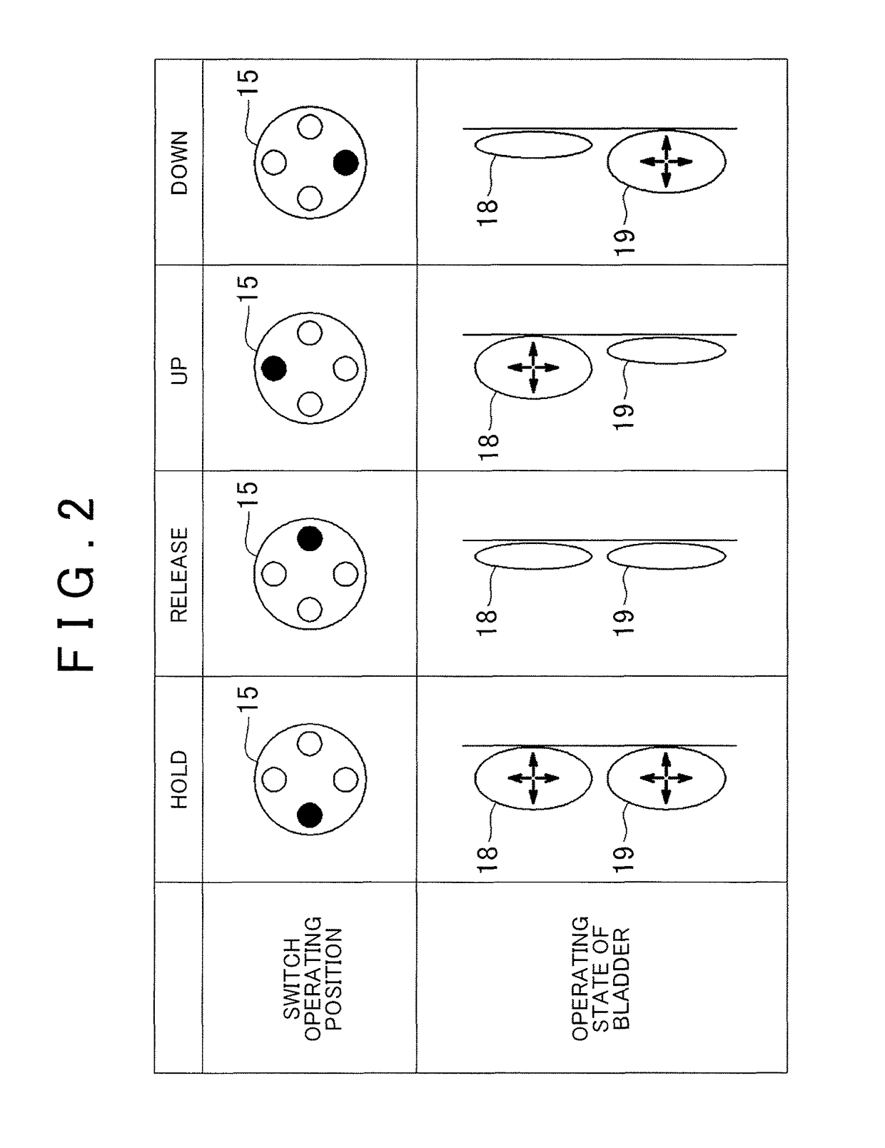
[0043]FIG. 2 is an operation explanatory view of the lumbar support in the first embodiment. An operating knob 15 of an operating switch is tilted and operated in four directions toward upper, lower, right and left sides shown by black circles in FIG. 2, to operate the ...
second embodiment
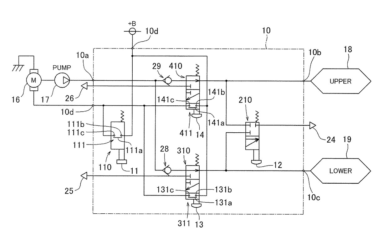
[0067]In the second embodiment, air is supplied to and discharged from the upper bladder 18 and the lower bladder 19 in each mode, when an operating knob 15 of an operation box 10 is operated in a corresponding direction. Hereinafter, each mode will be described.
[0068](Hold Mode) When the pusher 11 of the switch box 120 is pressed, the switch element 111 is turned on, and a motor 16 is operated. Consequently, the air is supplied from the discharge port of the pump 17, and the air flows through the switching valve of the switch box 120 and is further supplied to the upper bladder 18 and the lower bladder 19 via the check valves 30 and 31 to expand these bladders (see FIGS. 8 and 13).
[0069](Release Mode) When a pusher 12 of a switch box 210 is pressed, the lower bladder 19 and the upper bladder 18 communicate with an exhaust port 24, and the lower bladder 19 and the upper bladder 18 are both contracted (see FIGS. 8 and 11).
[0070](Up Mode) When a pusher 13 of the switch box 320 is pres...
third embodiment
[0075]In the third embodiment, when the operating knob 21 of an operation box 10 is operated in each direction, air is supplied to and discharged from the bladder 20 in a corresponding mode. Hereinafter, each mode will be described in detail.
[0076](Hold Mode) When a pusher (corresponding to a first operating body according to the present invention) 11 of the switch box 110 is pressed, a switch element 111 is turned on, and a motor 16 is operated. Consequently, the air is supplied from the discharge port of the pump 17, and the air is supplied to the bladder 20 via the check valve 32 to expand the bladder 20 (see FIGS. 9 and 10).
[0077](Release Mode) When a pusher 22 (corresponding to a second operating body according to the present invention) of the switch box 510 is pressed, the bladder 20 communicates with the discharge port 27, and the bladder 20 is contracted (see FIGS. 9 and 15).
[0078]FIGS. 16 to 18 show switch boxes 130, 220 and 330 (430) in a fourth embodiment of the present i...
PUM
 Abstract
Description
Claims
Application Information
 - R&D
- Intellectual Property
- Life Sciences
- Materials
- Tech Scout
- Unparalleled Data Quality
- Higher Quality Content
- 60% Fewer Hallucinations
Browse by: Latest US Patents, China's latest patents, Technical Efficacy Thesaurus, Application Domain, Technology Topic, Popular Technical Reports.
© 2025 PatSnap. All rights reserved.Legal|Privacy policy|Modern Slavery Act Transparency Statement|Sitemap|About US| Contact US: help@patsnap.com


