Dental or surgical compressed air handpiece and turbine for such a handpiece

a technology of compressed air and handpiece, which is applied in the field of handpieces, can solve problems such as conversion efficiency, and achieve the effects of promoting pressure drop, facilitating air return, and increasing pressure drop

Active Publication Date: 2018-01-30
BIEN AIR HLDG SA
View PDF10 Cites 0 Cited by
  • Summary
  • Abstract
  • Description
  • Claims
  • Application Information

AI Technical Summary

Benefits of technology

[0020]According to another advantage of the invention, the insert which serves to force the compressed air flow towards the blades of the moving wheel is mounted inside the discharge pipe arranged in the handpiece body and through which the air is discharged after striking the blades of the moving wheel. This arrangement facilitates the air return and thus greatly promotes the pressure drop between the pressure of the compressed air before it strikes the turbine blades and the pressure of the air exiting the handpiece head after striking the turbine blades. The higher the pressure drop, the better the conversion between the pneumatic energy of the compressed air and the kinetic energy of the turbine. This pressure drop is further amplified by the fact that the insert is mounted coaxially inside the discharge pipe. The diameter of the discharge pipe can thus be increased, which makes it possible to bring the air pressure inside the handpiece head down to values close to atmospheric pressure. Finally, the conversion efficiency between pneumatic energy and kinetic energy is further improved because the air flow occurs with minimal turbulence and thus minimal losses. Further, the operating noise of the handpiece is reduced and virtually no air is discharged into the patient's mouth.
[0021]According to another advantage of the invention, the injection means force the compressed air flow so that the compressed air flow strikes the blades of the moving turbine wheel in a tangential direction to the outer diameter of the moving wheel. Consequently, this ensures that maximum torque is exerted by the air flow on the turbine blades, which substantially increases the power provided by the turbine. By way of example, the power provided by current compressed air handpieces is on the order of 13 watts, whereas the measured power of a compressed air handpiece according to the invention is on the order of 20 watts. Therefore, with a compressed air handpiece according to the invention practitioners enjoy increased power, which allows them to work more quickly or to perform treatments which, until now, would have been difficult to achieve using a compressed air handpiece due to the insufficient power available.
[0022]The present invention also concerns a turbine for a compressed air handpiece for dental or surgical use, said turbine including a moving wheel from the periphery of which extend a plurality of regularly spaced blades, the turbine being characterized in that each of the blades is formed of a first surface, which extends from the outer diameter of the moving wheel and which leads to a second surface, which extends along a radius of the moving wheel.
[0023]According to a preferred embodiment of the invention, the first surface extends from the outer diameter of the moving wheel to a point on the radius of the moving wheel from which the second surface extends radially to the outer diameter of the moving wheel.
[0024]Finally, according to another feature of the invention, the blades are associated in pairs in a stepped manner, each blade being separated from its corresponding blade by a notch which extends in the direction of the compressed air flow, so that the air flow is divided into two equal parts at the moment it reaches the notch. The object of this notch is to reduce the transit time from one blade to the next in order to limit the mechanical power losses of the turbine.
[0025]The first surface leads the compressed air exiting the injection means towards the second surface. As the second surface extends along a radius of the moving wheel and the compressed air flow is channelled in a tangential direction to the outer diameter of the moving wheel, the compressed air flow falls perpendicularly onto the second surface of the blade and then turns back. The mechanical power provided by a turbine increases with the angle of deviation of the compressed air. In the case of the present invention, the angle of deviation of the compressed air is 180°, which corresponds to optimum conversion between the pneumatic energy of the compressed air and the kinetic energy of the turbine.

Problems solved by technology

A recurrent problem facing designers of compressed air handpieces lies in the conversion efficiency between the pneumatic energy of the compressed air and the kinetic energy of the moving turbine wheel.

Method used


Image

  • Dental or surgical compressed air handpiece and turbine for such a handpiece
  • Dental or surgical compressed air handpiece and turbine for such a handpiece
  • Dental or surgical compressed air handpiece and turbine for such a handpiece

Examples


Embodiment Construction

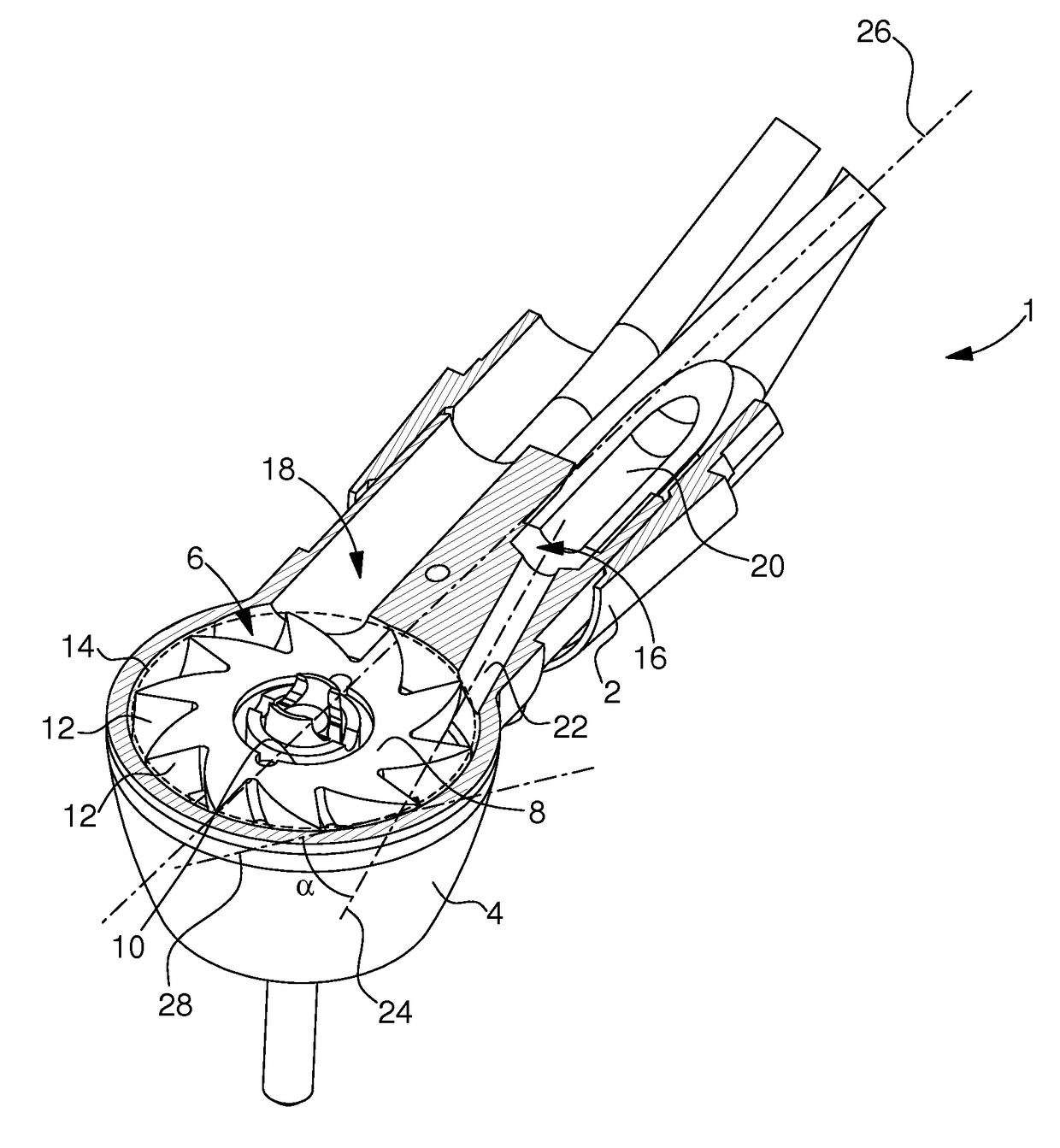
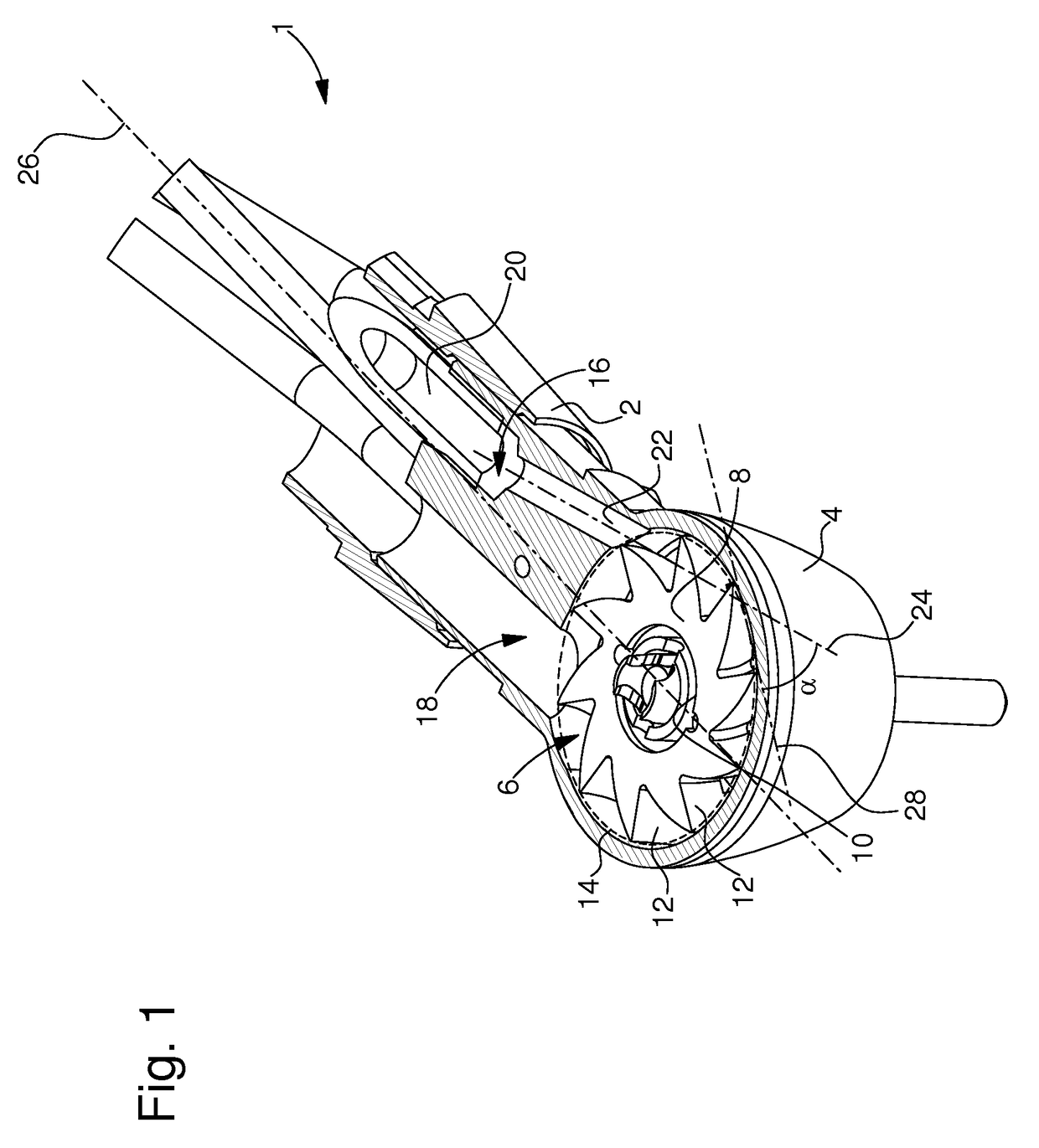
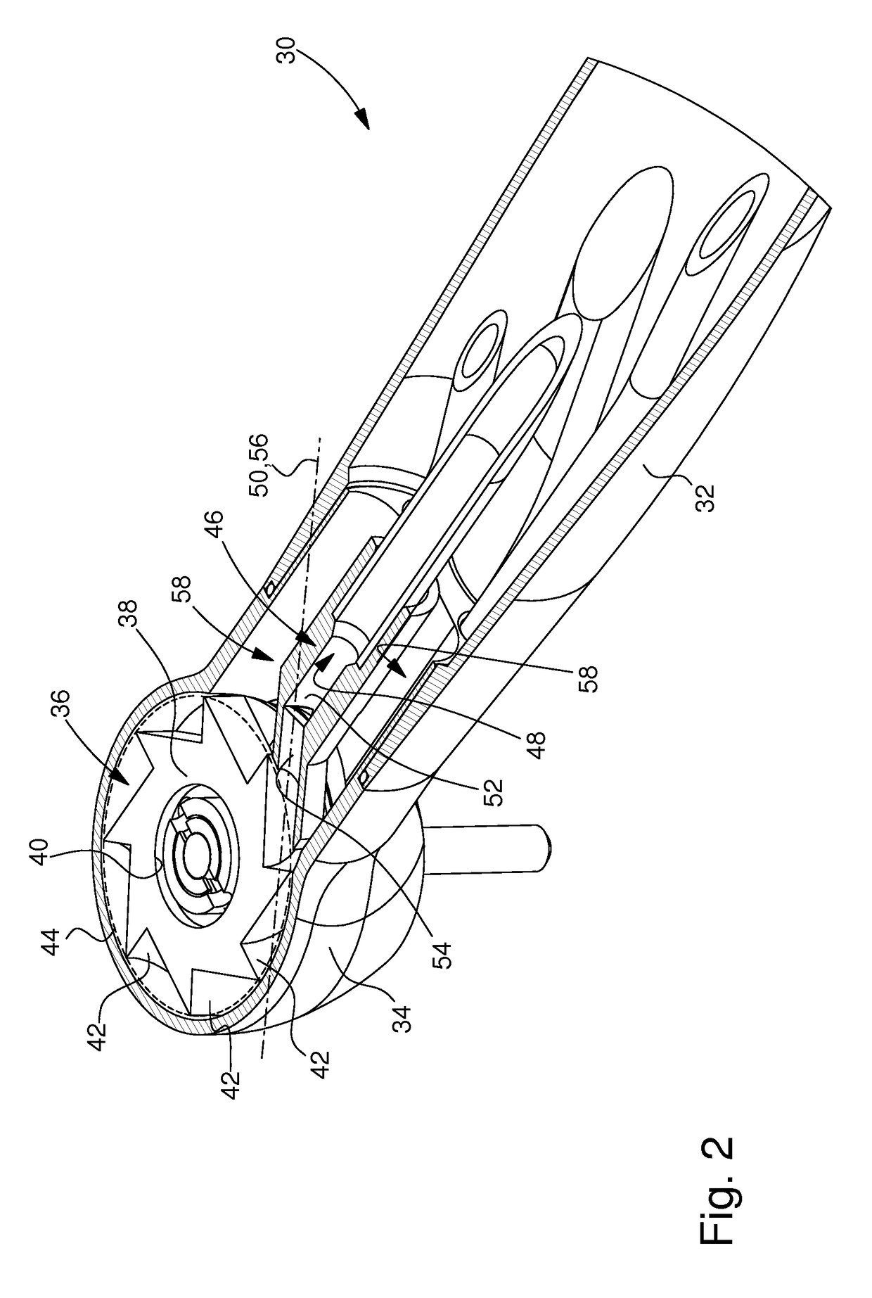
[0035]The present invention proceeds from the general inventive idea which consists in taking any measures necessary to increase the mechanical power that can be provided by a compressed air handpiece. To this end, the present invention attempts to optimise the conversion efficiency between the pneumatic energy of the compressed air and the kinetic energy of the moving turbine wheel. Indeed, the mechanical power that the compressed air handpiece can deliver depends on this conversion efficiency. This conversion efficiency is, in particular, closely linked to the air flow conditions inside the turbine head. Indeed, it is known that, whereas part of the compressed air injected into the handpiece head drives and goes around the turbine, another part of the compressed air simply ricochets onto the turbine blades and thus tends to turn back creating turbulence in the handpiece head. By arranging the air discharge means at least in the area into which this air is injected, the present inv...


PUM


Abstract

Compressed air handpiece including a handle connected to a head housing a turbine. The turbine includes a moving wheel from a periphery of which extends a plurality of blades which define an outer diameter of the moving wheel. The handpiece also includes injection means, whose function is to direct onto the blades of the moving wheel a compressed air flow whose pneumatic energy is converted into kinetic energy when the compressed air flow strikes the blades of the moving wheel. The injection means take the form of an independent insert inside which is arranged a compressed air flow feed pipe and which is mounted inside the handle of the handpiece.

Description

[0001]This application claims priority from European Patent Application No. 13196222.7 filed Dec. 9, 2013 the entire disclosure of which is incorporated herein by reference.FIELD OF THE INVENTION[0002]The present invention concerns a dental or surgical compressed air handpiece and a turbine for such a handpiece. The present invention concerns, in particular, a compressed air handpiece having increased power.BACKGROUND OF THE INVENTION[0003]The present invention concerns the field of handpieces for dental or surgical use. There are two families of handpieces: contra-angle handpieces which are equipped with an electrical motor and handpieces which include a turbine driven by compressed air.[0004]We are concerned here with compressed air handpieces. In very simple terms, these compressed air handpieces include a head which houses a turbine. This turbine includes a compressed air feed pipe and a moving wheel provided with a plurality of regularly spaced blades at the periphery thereof. ...

Claims


Application Information

Patent Timeline
Patent Type & Authority Patents(United States)
IPC IPC(8): A61C1/05A61C1/12A61B17/16
CPCA61C1/05A61C1/12A61B17/1628
Inventor FARINE, LAURENT
Owner BIEN AIR HLDG SA
Why Eureka
Try Eureka