
FEL system with homogeneous average output

a technology of average output and charge particle, applied in the direction of laser details, excitation process/apparatus, electrical apparatus, etc., can solve the problems of “noisy” wavelength output and detrimental to beam quality, and achieve the effect of reducing the “noise” in wavelength outpu

Active Publication Date: 2018-01-16
JEFFERSON SCI ASSOCS LLC
View PDF6 Cites 0 Cited by
  • Summary
  • Abstract
  • Description
  • Claims
  • Application Information

AI Technical Summary

Benefits of technology

This method produces a smooth, time-averaged wavelength spectrum with independent control of multiple bunch trains, reducing noise and improving beam quality by generating a broader, smoother output in a single beamline, enabling rapid wavelength variation.

Problems solved by technology

Depending on system architecture FELs typically do, on a drive-electron-bunch-by-bunch basis, produce “noisy” wavelength output, which is detrimental to the beam quality.

Method used


Image

  • FEL system with homogeneous average output
  • FEL system with homogeneous average output
  • FEL system with homogeneous average output

Examples


Embodiment Construction

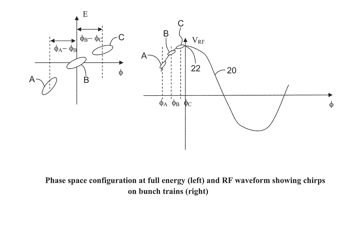
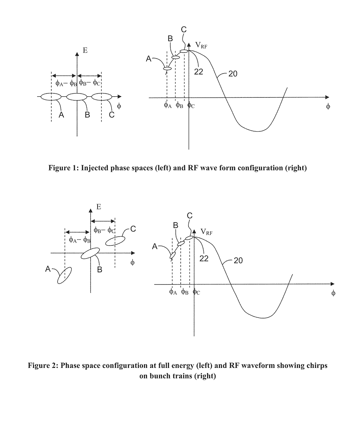
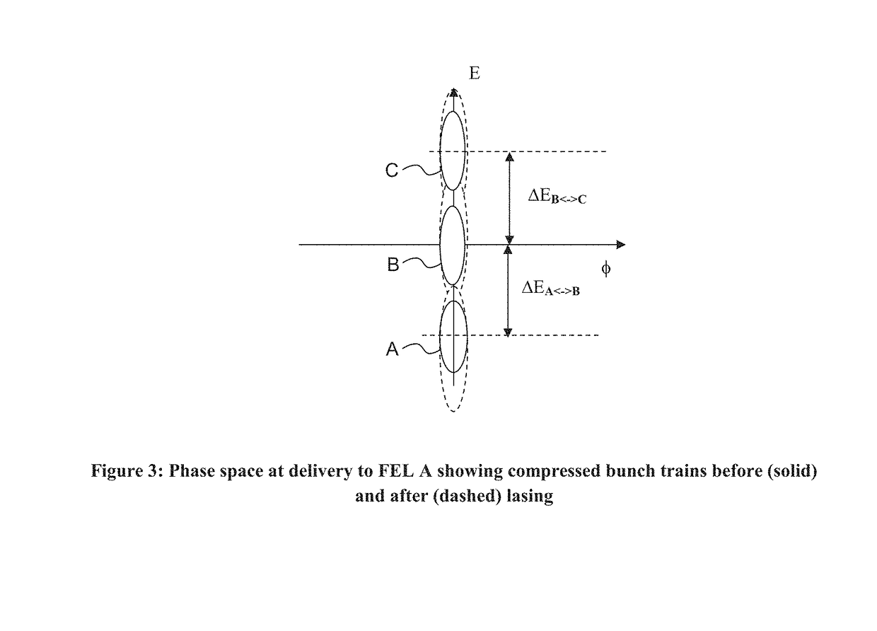
[0015]The current invention includes a method of varying the output of a free electron laser (FEL) on very short time scales to produce a slightly broader, but smooth, time-averaged wavelength spectrum.

[0016]The meaning of terms as used herein includes:[0017]1) The term “linac” refers to a linear accelerator, which is a straight section of a particle accelerator system in which beam energy is boosted by a chain of RF cavities. As an example, at the Continuous Electron Beam Accelerator Facility (CEBAF) in Newport News, Va., each CEBAF linac contains 160 RF cavities that can boost the beam energy by 600 MeV. The particle accelerator is the machine or equipment used to transfer kinetic energy to charged particles in order to increase the momentum of the particle.[0018]2) The term “energy compression” is the application of RF-energy to reduce the energy spread of the beam from the linear accelerator. The benefits of the energy compression will be to lower the energy spread of the beam.[...


PUM


Abstract

A method of varying the output of a free electron laser (FEL) on very short time scales to produce a slightly broader, but smooth, time-averaged wavelength spectrum. The method includes injecting into an accelerator a sequence of bunch trains at phase offsets from crest. Accelerating the particles to full energy to result in distinct and independently controlled, by the choice of phase offset, phase-energy correlations or chirps on each bunch train. The earlier trains will be more strongly chirped, the later trains less chirped. For an energy recovered linac (ERL), the beam may be recirculated using a transport system with linear and nonlinear momentum compactions M56, which are selected to compress all three bunch trains at the FEL with higher order terms managed.

Description

CROSS-REFERENCE TO RELATED APPLICATIONS[0001]This application claims the priority of Provisional U.S. Patent Application Ser. No. 61 / 991,925 filed May 12, 2014.GOVERNMENT LICENSE RIGHTS[0002]This invention was made with government support under Management and Operating Contract No. DE-AC05-06OR23177 awarded by the Department of Energy. The United States Government has certain rights in the inventionFIELD OF THE INVENTION[0003]The present invention relates to charged particle beams and more particularly to a method of varying the output of a free electron laser (FEL) on very short time scales to produce a slightly broader, but smooth, time-averaged wavelength spectrum.BACKGROUND OF THE INVENTION[0004]Depending on system architecture FELs typically do, on a drive-electron-bunch-by-bunch basis, produce “noisy” wavelength output, which is detrimental to the beam quality.[0005]Accordingly, it would be desirable to reduce the “noise” and produce a slightly broader, but smooth, time-averag...

Claims


Application Information

Patent Timeline
Patent Type & Authority Patents(United States)
IPC IPC(8): H01S3/09H01S3/10
CPCH01S3/10H01S3/0903
Inventor DOUGLAS, DAVID R.LEGG, ROBERTWHITNEY, R. ROYNEIL, GEORGEPOWERS, THOMAS JOSEPH
Owner JEFFERSON SCI ASSOCS LLC
Learn More