
Display apparatus and method of manufacturing the same

a technology of display apparatus and mold frame, which is applied in the direction of non-linear optics, identification means, instruments, etc., can solve the problems of liquid crystal display apparatus, difficult detection of misalignment, and substrate and mold frame misalignment, and achieve the effect of reducing the defect of the display apparatus due to such misalignmen

Inactive Publication Date: 2018-01-16
SAMSUNG DISPLAY CO LTD
View PDF14 Cites 6 Cited by
  • Summary
  • Abstract
  • Description
  • Claims
  • Application Information

AI Technical Summary

Benefits of technology

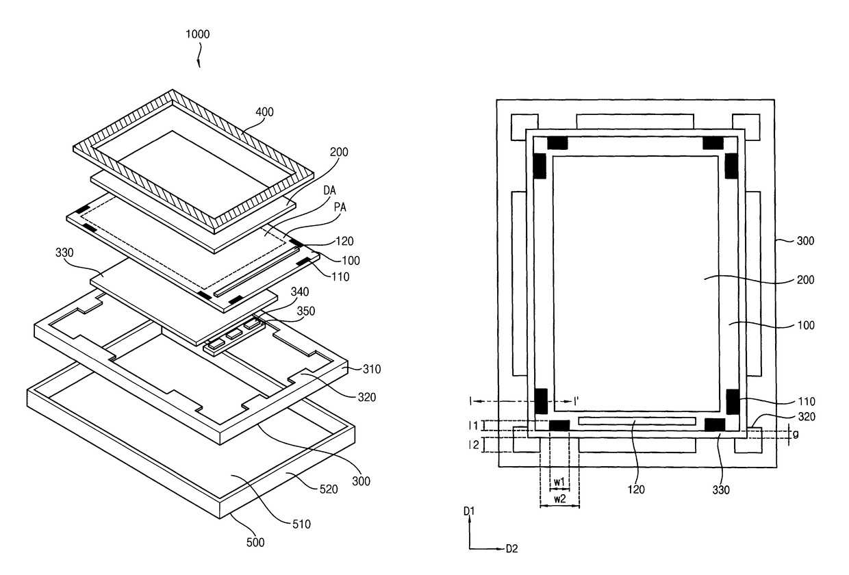
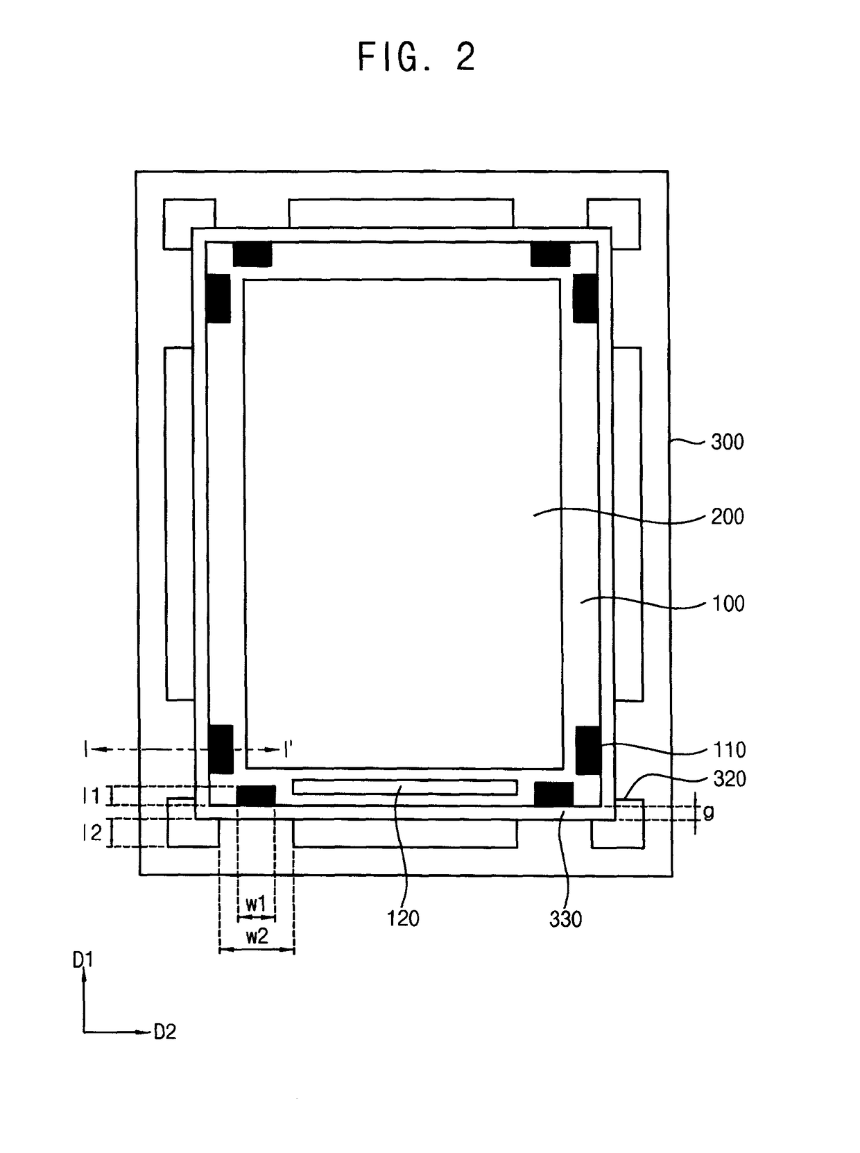
[0010]Exemplary embodiments provide a display apparatus including an alignment mark on a display panel of the display apparatus, thereby decreasing a misalignment between elements of the display apparatus.
[0033]In accordance with one or more exemplary embodiment, in a display apparatus, when a display panel is combined with a mold frame, a misalignment of the display panel with respect to the mold frame may be easily detected by an alignment mark of the display panel disposed on a transparent substrate of the display panel. Therefore, a defect of the display apparatus due to such misalignment may decrease.

Problems solved by technology

When a substrate of the liquid crystal display panel is disposed on the protrusion of the mold frame, the substrate and the mold frame may be misaligned.
However, since the substrate includes a transparent material and the mold frame is white, a misalignment may be difficult to detect.
Therefore, since misalignment may be difficult to detect, a defect of a liquid crystal display apparatus due to the misalignment may undesirably increase.
Therefore, a defect of the display apparatus due to such misalignment may decrease.

Method used


Image

  • Display apparatus and method of manufacturing the same
  • Display apparatus and method of manufacturing the same
  • Display apparatus and method of manufacturing the same

Examples


Embodiment Construction

[0044]In the drawings, the size and relative sizes of layers and regions may be exaggerated for clarity. It will be understood that when an element or layer is referred to as being “on” or “connected to” another element or layer, the element or layer can be directly on or connected to another element or layer or intervening elements or layers. In contrast, when an element is referred to as being “directly on” or “directly connected to” another element or layer, there are no intervening elements or layers present. As used herein, connected may refer to elements being physically and / or electrically connected to each other. Like numbers refer to like elements throughout. As used herein, the term “and / or” includes any and all combinations of one or more of the associated listed items.

[0045]It will be understood that, although the terms first, second, third, etc., may be used herein to describe various elements, components, regions, layers and / or sections, these elements, components, reg...


PUM

PropertyMeasurementUnit
lengthaaaaaaaaaa
widthaaaaaaaaaa
widthaaaaaaaaaa

Abstract

A display apparatus includes a display panel and a mold frame. The display panel includes a display area, a peripheral area surrounding the display area, an alignment mark on the peripheral area, and a cover element overlapping the alignment mark to cover the alignment mark. The mold frame has a frame shape configured to receive the display panel. The mold frame includes a panel guide protrusion protruding from an inner surface of the mold frame, and the panel guide protrusion is adjacent to the alignment mark.

Description

[0001]This application claims priority to Korean Patent Application No. 10-2013-0136580, filed on Nov. 11, 2013, and all the benefits accruing therefrom under 35 U.S.C. §119, the disclosure of which is incorporated by reference herein in its entirety.BACKGROUND[0002](1) Field[0003]Exemplary embodiments relate to a display apparatus and a method of manufacturing the same. More particularly, exemplary embodiments relate to a display apparatus and a method of manufacturing the same which decreases a defect of a product.[0004](2) Description of the Related Art[0005]A liquid crystal display (“LCD”) panel is one of a flat panel display, which is used broadly. Examples of the flat panel display include, but are not limited to, the LCD panel, a plasma display panel (“PDP”) and an organic light emitting display panel (“OLED”).[0006]A liquid crystal display apparatus including the liquid crystal display panel applies voltages to specific molecules of liquid crystal to convert arrangements of ...

Claims


Application Information

Patent Timeline
Patent Type & Authority Patents(United States)
IPC IPC(8): G02F1/1333
CPCG02F1/133308G02F2001/133354G02F2001/133322G02F2001/133317G02F1/133317G02F1/133322G02F1/133354G09F9/00G09F9/35
Inventor KIM, JOO-SUCHYUN, MIN-GWAN
Owner SAMSUNG DISPLAY CO LTD
Learn More