
Rod end wear prevention

a technology of wear prevention and rod end, which is applied in the direction of sliding contact bearings, mechanical equipment, transportation and packaging, etc., can solve the problems of limiting the service life, contact between the rod end and the clevis, and wear of one of the components

Active Publication Date: 2018-01-09
SIKORSKY AIRCRAFT CORP
View PDF21 Cites 3 Cited by
  • Summary
  • Abstract
  • Description
  • Claims
  • Application Information

AI Technical Summary

Benefits of technology

This patent describes a way to prevent wear and tear on rods and brackets in a rod and bracket assembly or clevis and rod assembly. It includes a bushing assembly with a wear pad that is positioned between the bracket or clevis and the inner face of the component to prevent wear and damage. The technical effect of this invention is to prolong the lifespan of rods and brackets, which can save time, money, and hassle in the long run.

Problems solved by technology

The bearing however, may also allow rolling of the rod about the rod axis, possibly resulting in contact between the rod end and the clevis.
This contact manifests itself in rubbing / chafing between the two components resulting in wear of one of the components, depending on material hardness, and limiting of the service life thereof.

Method used


Image

  • Rod end wear prevention
  • Rod end wear prevention
  • Rod end wear prevention

Examples


Embodiment Construction

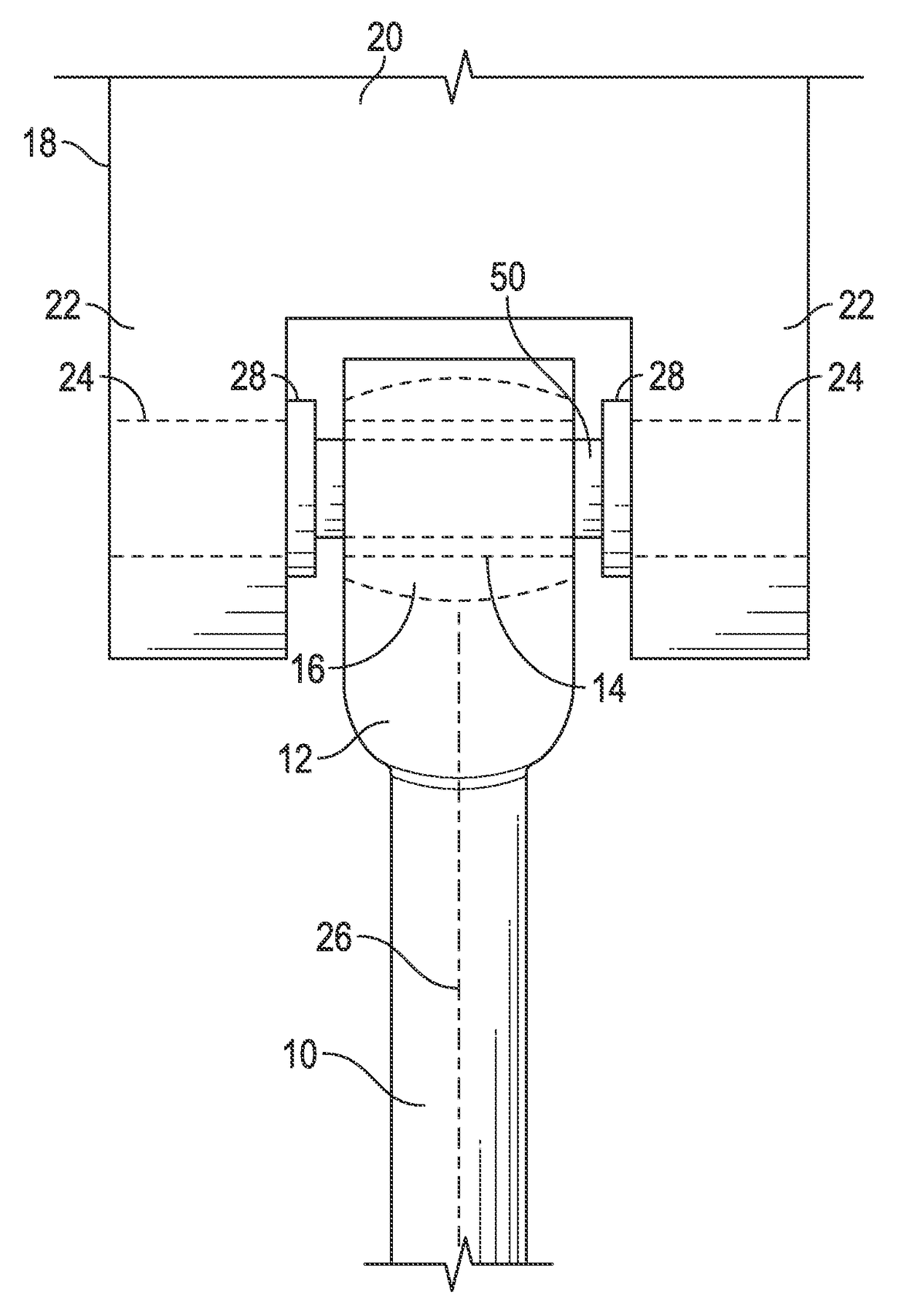
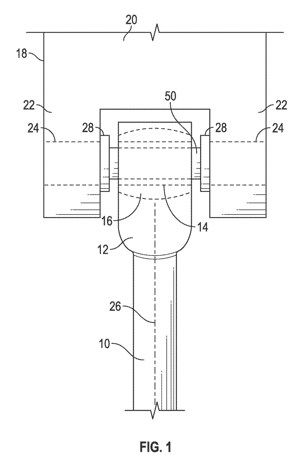
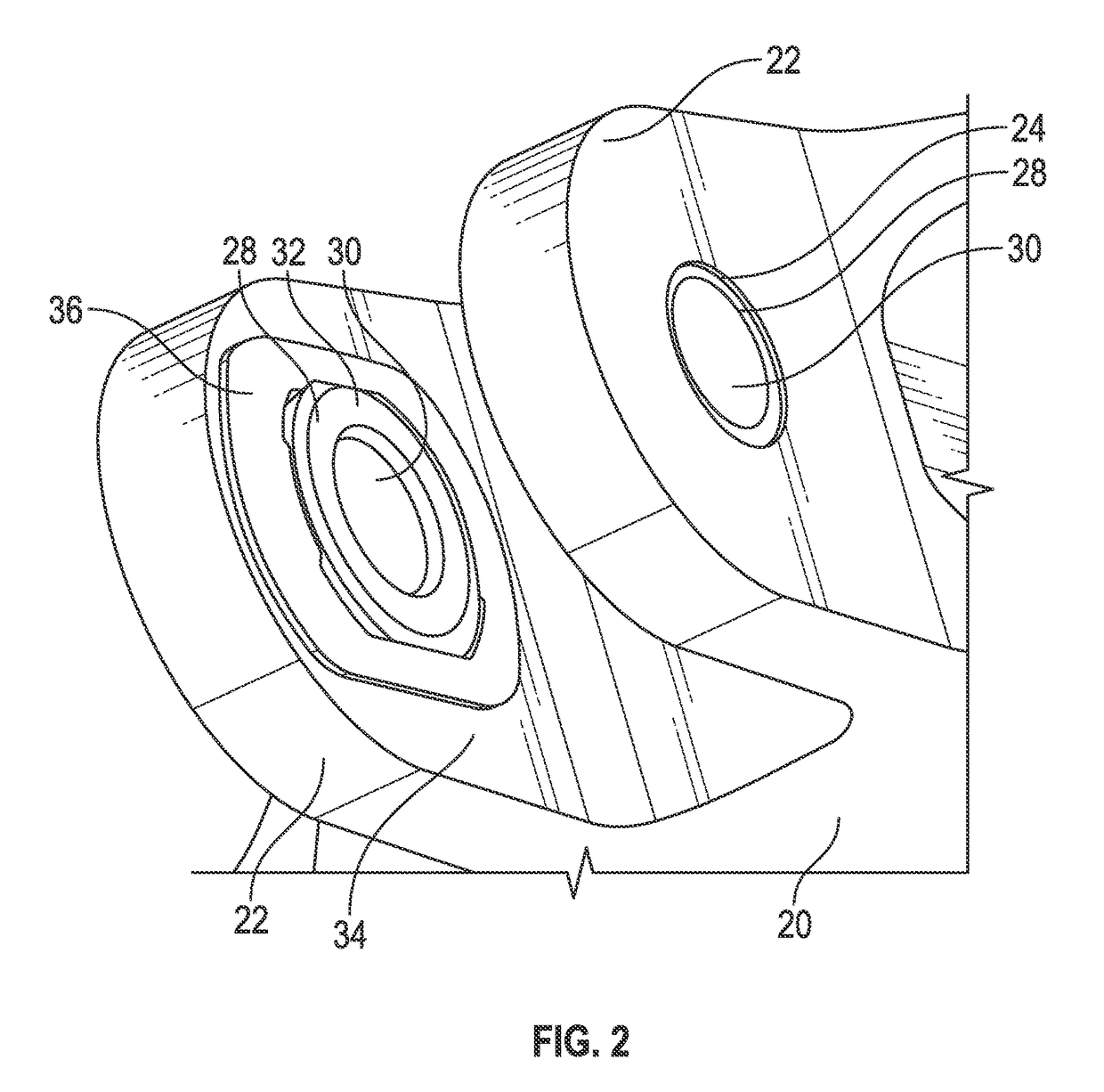
[0012]Shown in FIG. 1 is an embodiment of a rod and clevis joint arrangement. The joint may be of the type used in a variety of applications including, for example, actuation systems, rotors, landing gear, flight controls, and airframes of aircraft and other technologies. The arrangement includes a rod 10 having a rod end 12 including an eyelet 14. The eyelet 14 may include a bearing 16 disposed thereat, for example, a monoball bearing. The arrangement also includes a bracket, for example, a clevis 18, having a clevis base 20 and one or more clevis legs 22 extending from the clevis base 20. Each clevis leg 22 has a clevis hole 24 extending therethrough. The joint is arranged such that the rod end 12 is positioned adjacent to one or between two of the clevis legs 22, and a pin 50 or other fastener is extended from a first clevis hole 24a through the eyelet 14 and, in some cases, into a second clevis hole 24b. The presence of the bearing 16 allows for rotation of the rod 10 about a ro...


PUM


Abstract

A rod and bracket assembly includes a bracket with a rod connected to the bracket via a fastener extending through a bracket hole. A bushing assembly is positioned at the bracket hole and includes a bushing having a bushing flange and a wear pad positioned between the bushing flange and an inner face of the bracket to prevent wear of the bracket and / or the rod in the event that the rod rolls about its own axis. A clevis assembly for a clevis and rod assembly includes a clevis having one or more clevis legs extending from a clevis base and a bushing assembly located at a clevis hole. The bushing assembly includes a bushing having a bushing flange and a wear pad disposed between the bushing flange and an inner face of the clevis leg to prevent wear of the clevis leg and / or the rod assembly.

Description

BACKGROUND[0001]The subject matter disclosed herein relates to rod and clevis joints and, more specifically, to anti-chafing solutions for rod and clevis joints.[0002]Rod and clevis joints are used in a variety of applications including, for example, actuation systems, rotors, landing gear, flight controls, and airframes of aircraft and other technologies. The typical rod and clevis joint includes a clevis, and a rod that fits between two arms of the clevis. A pin extends through holes in the clevis arms and through an eye in the rod to secure the rod to the clevis. In some rods, a rod end includes a monoball bearing in the eye to support the rod in the clevis and to allow for misalignment and relative motion between the rod and clevis. The bearing however, may also allow rolling of the rod about the rod axis, possibly resulting in contact between the rod end and the clevis. This contact manifests itself in rubbing / chafing between the two components resulting in wear of one of the c...

Claims


Application Information

Patent Timeline
Patent Type & Authority Patents(United States)
IPC IPC(8): F16C23/04F16C11/04F16C17/04F16C11/02
CPCF16C23/045F16C11/045Y10T403/32606F16C17/04F16C2326/43F16C11/02
Inventor HALCOM, LANCE
Owner SIKORSKY AIRCRAFT CORP
Learn More