
Energy storage system and modular communication

a technology of energy storage and modular communication, applied in transmission systems, power oscillation reduction/prevention, ac network load balancing, etc., can solve the problems of battery storage devices, devices that have been planned so far do not fulfill localized tasks, and the operation method is not adapted to stabilize or improve the quality of small local power supply systems. , to achieve the effect of improving the quality of local grids

Active Publication Date: 2018-01-02
ENRICHMENT TECH CO LTD
View PDF6 Cites 3 Cited by
  • Summary
  • Abstract
  • Description
  • Claims
  • Application Information

AI Technical Summary

Benefits of technology

[0007]It is an object of the present invention to provide an effective energy storage system which allows achieving an improvement in the quality of local grids and, at the same time, the security of energy supplies for non-local power supply grids as required.
[0019]In a further embodiment, the master module comprises a first test unit which is provided to check the received external control commands for plausibility and / or origin and to transmit to the master control unit a positive or negative first test result before the master control unit stores the received external control commands. This prevents unauthorized persons from gaining access to the system or module core, i.e., the master control unit. This contributes to the operational safety of the energy storage system towards the outside world and to the security of energy supplies. In case of the received non-localized and localized control and system tasks, the origin can, for example, be included in the received data packet and accordingly be read by the first test unit and compared with the expected data structure of the origin identifier. Herein, the origin can, for example, be transmitted as hash value which the first test unit can compare with the hash values for allowed data sources for non-localized and localized control and system tasks, which it has available. The origin is verified to be allowed, if the available hash value is identical with the received hash value. The non-localized and localized control and system tasks may also be transmitted in a coded manner, wherein the decoding key is characteristic of the particular origin. If the non-localized and the localized control and system tasks can be decoded using a decoding key, this decoding key is characteristic of the origin of the data received. For example, the plausibility of the received data can also be checked negatively, i.e., the localized and non-localized control and system tasks do not represent any tasks which cannot be carried out due to the system storage capacity and the system output or the tasks contain meaningless data in terms of data format. Therein, a plausibility check can comprise the calculation of a checksum, a data sum check and / or an encryption with subsequent successful decryption.
[0024]In a further embodiment, the slave module also comprises an interface for receiving external control commands regarding the localized and non-localized control and system tasks to be carried out, and, in the event of a failure of the present master module or the present master control unit, the slave control unit is formed to store the external control commands and to control the other slave modules as new master control unit. Since the slave module is also able to receive external control commands, it is also adapted to control the energy storage system in an overall manner. Thereby, a redundancy in the management (control) of the energy storage system is provided, with the result that the operational safety and availability of the energy storage system are ensured even in the event of a failure of the master control unit. The data line(s) connect(s) not only the master control unit to all slave control units but also all slave control units to each other (mesh network). As a result, a slave control unit can assume the task of controlling the energy storage system at any time and as a substitute. In a preferred embodiment, the master control unit is provided to establish a hierarchy according to which the slave control units assume the task of controlling the other slave modules in the event of a failure of the present master module or the present master control unit and to transmit said hierarchy to the slave modules. Based on the hierarchy, the slave module determined can immediately continue to control the energy storage system as the new master module. As a result, continued availability and security of the system are ensured in the event of partial failures in the energy storage system.

Problems solved by technology

This operating method is not adapted to stabilize or improve the quality of a small local power supply systems having a demand for electricity that is rather negligible as compared with the capacity of the pumped storage power station.
However, the devices that have been planned so far do not fulfill any localized tasks.
Due to their immanent relationships between output, capacity and aging, however, battery storage devices are, as a matter of principle, not very well suited for such applications with a plurality of load cycles per day and degrade rapidly because of temperature influences, system failures and operating errors.
For this reason, battery storage devices require highly intensive maintenance.
Due to their high fire and chemical risks, battery storage devices additionally present an environmental and / or water hazard and are highly complex in terms of protection and security.
In general, decentralized energy storage systems are optimized for stabilizing the local demand for electricity and are neither designed nor qualified for delivering reserve energy to support the non-local power supply grid.
Such systems cannot contribute to fulfilling the demands of all power supply grids.
An interconnection of the decentralized storage systems to form a system that is operated both locally and non-locally has not been achieved so far.

Method used


Image

  • Energy storage system and modular communication
  • Energy storage system and modular communication
  • Energy storage system and modular communication

Examples


Embodiment Construction

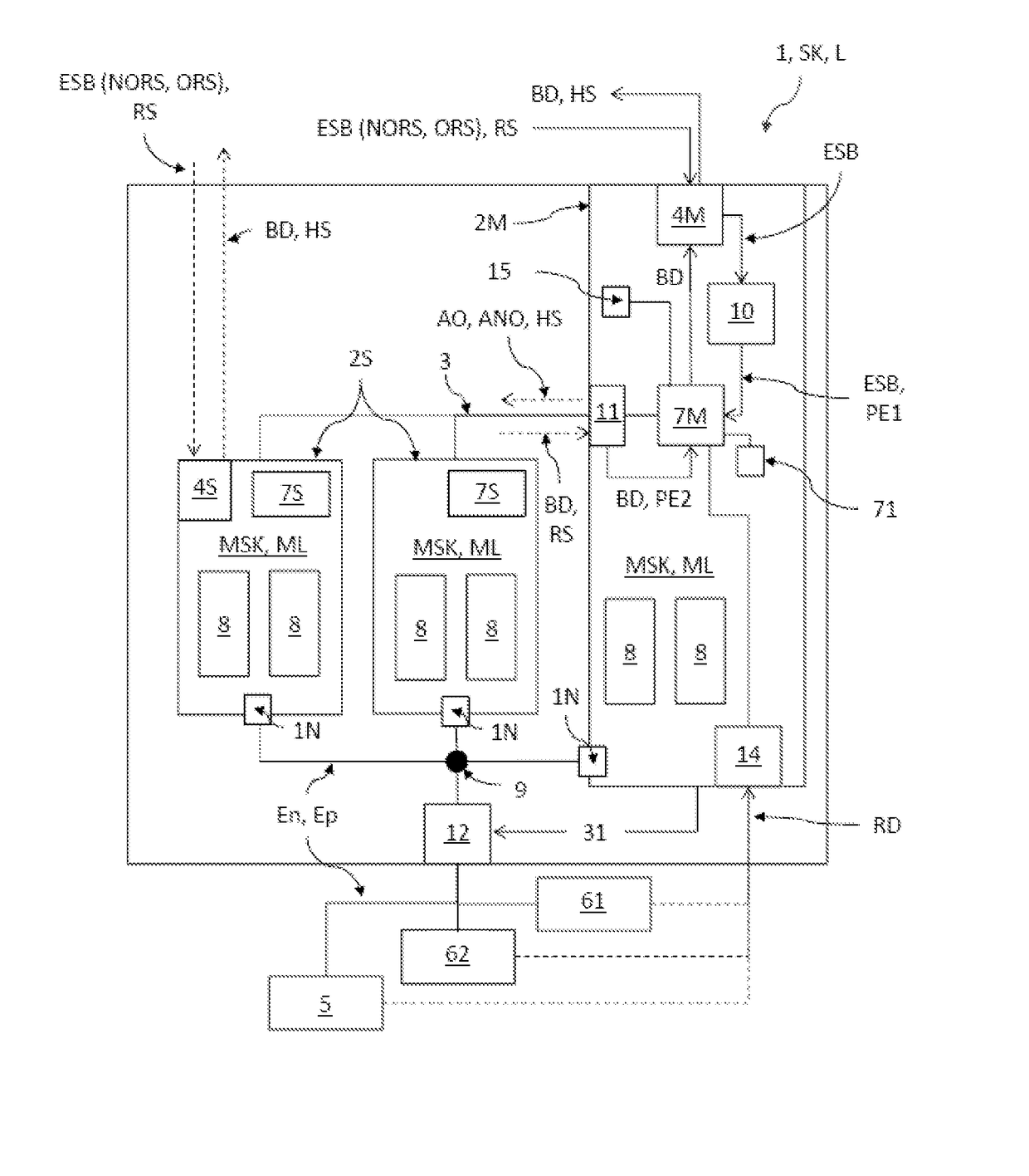
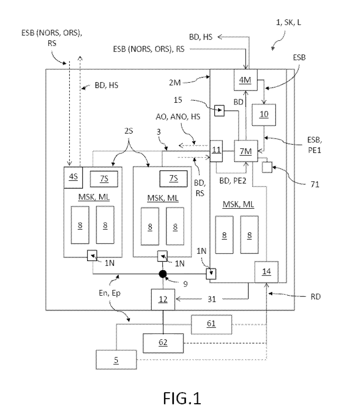
[0072]FIG. 1 shows an exemplary embodiment of the energy storage system 1 according to the invention. In this embodiment, the energy storage system 1 has three energy storage modules 2M, 2S each having two flywheel energy storage units 8 for reversible storage of energy per energy storage module 2M, 2S each having a module storage capacity MSK and a module output ML. The three energy storage modules 2M, 2S are split between a master module 2M for controlling the energy storage module 1 and two slave modules 2S. The embodiment shown here is only exemplary. The number of energy storage modules 2M, 2S per energy storage system 1 depends on the particular application desired and therefore vary strongly. Use can also be made of energy storage systems 1 having only one single energy storage module 2M which, in the present case, is a master module 2M. In the illustrated instance, the energy storage modules 2M, 2S are connected via a common connection point 9, with the result that their mod...


PUM


Abstract

An energy storage system is provided that is adapted to simultaneously carry out control and system tasks in non-local and local power supply grids and to a method for operating such an energy supply system. The energy storage system has a modular structure and comprises more than one energy storage modules that are connected to each other via data lines. One of the energy storage modules is provided as master module and the others are provided as slave modules and the master module is configured for the overall control of all energy storage modules connected to the data line. At least the master module comprises at least one interface for receiving external control commands regarding the localized and non-localized control and system tasks to be carried out and a master control unit for storing and carrying out the external control commands.

Description

RELATED APPLICATIONS[0001]The present invention is a U.S. National Stage under 35 USC 371 patent application, claiming priority to Serial No. PCT / EP2013 / 068718, filed on 10 Sep. 2013; which claims priority from Ep 12186464.9, filed 28 Sep. 2012, the entirety of both of which are incorporated herein by reference.FIELD OF THE INVENTION[0002]The invention relates to an energy storage system that is adapted to simultaneously carry out control and system tasks in non-local and local power supply grids, to a master module for use in such an energy storage system, and to a method for operating such an energy storage system.BACKGROUND OF THE INVENTION[0003]The energy for operating a power supply grid is supplied by various and different types of power stations. Herein, most of the power stations, such as nuclear power stations, coal-fired power stations, gas-fired power stations, wind turbines, biogas plants, or solar power plants, are nothing but energy generators for feeding energy into t...

Claims


Application Information

Patent Timeline
Patent Type & Authority Patents(United States)
IPC IPC(8): H02J3/24H02J3/38H02J3/30H02J3/00
CPCH02J3/24H02J3/005H02J3/382H02J3/30Y10T307/32Y02E60/16
Inventor VON DEM ESCHE, RAINERSCHAFER, CHRISTOPHTREPPMANN, CHRISTOPH
Owner ENRICHMENT TECH CO LTD
Learn More