
EVAP system with valve to improve canister purging

a technology of evap system and canister, applied in the direction of electric control, charge feed system, non-fuel substance addition to fuel, etc., can solve the problems of fuel vapor generation, carbon desorption of fuel vapor, fuel vapor leakage or permeation of fuel tank, etc., to reduce vapor emissions and emissions.

Inactive Publication Date: 2017-12-19
FORD GLOBAL TECH LLC
View PDF24 Cites 7 Cited by
  • Summary
  • Abstract
  • Description
  • Claims
  • Application Information

AI Technical Summary

Benefits of technology

The patent text discusses the issue of purging efficiency in fuel vapor storaging devices. The issue is that current devices do not evenly distribute air during purging, which can result in decreased desorption rates of fuel vapor. The patent describes a mixing valve that can be positioned upstream of a fuel vapor canister to increase turbulence in air entering the canister and improve purging efficiency. This can help to decrease fuel vapor emissions from vehicles and prevent the canister from reaching maximum capacity. The patent also mentions the use of an actuator to adjust the position of the mixing valve and a controller to adjust the valve based on oxygen sensor inputs. Overall, the patent provides a solution for improving purging efficiency and reducing fuel vapor emissions from vehicles.

Problems solved by technology

This pressure change can also cause vapor generation.
The fuel vapors may leak or permeate from the fuel tank if not properly sequestered.
During purging operation, fresh air may be introduced into the canister causing desorption of the fuel vapors from the carbon in the canister.
However, the fuel vapor storing device disclosed in U.S. Pat. No. 8,246,729 does not provide a desired amount of flow distribution in the device during purging.
Specifically, the tubular diffuser may not generate flow patterns which evenly distribute the airflow through the device when purged.
As a result, a desired amount of fuel vapor may not be purged from the device in a desired period of time, preventing the device from being completely purged.
This may be particularly problematic in plug-in electric hybrid vehicles (PHEV) where high purge rates are desired due to the limited window of engine combustion operation in the vehicle.

Method used


Image

  • EVAP system with valve to improve canister purging
  • EVAP system with valve to improve canister purging
  • EVAP system with valve to improve canister purging

Examples


Embodiment Construction

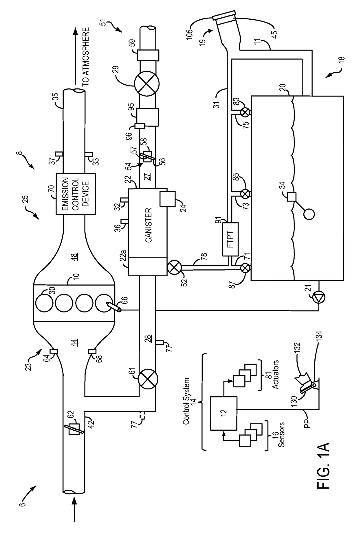
[0015]The following detailed description relates to systems and methods for improving purging of a fuel vapor canister included in an engine system, such as the engine system of FIGS. 1A and 1B. The fuel vapor canister may be coupled to an engine intake via a canister purge valve. Stored fuel vapors in the fuel vapor canister may be purged to the intake by opening of the canister purge valve, and a canister vent valve. Thus, during purging operation of the canister, the purge valve and vent valve may be opened to allow fresh, ambient air to be drawn through the canister via vacuum generated in an intake manifold. As air flows through the canister, it may come into contact with fuel vapors stored in the canister, and may cause the fuel vapors to be desorbed and purged from the canister.

[0016]However, airflow through the canister may be uneven. Thus, air flowing through the canister may be restricted to only a portion of the canister, and air may not reach all areas of the canister du...


PUM


Abstract

Systems and methods are provided for an evaporative emissions control system. In one example, a system for an engine may comprise a fuel vapor canister, a mixing valve positioned in a fresh air line upstream of the vapor canister, and an actuator physically coupled to the mixing valve for adjusting a position of the mixing valve to increase turbulence in air entering the vapor canister. The position of the mixing valve may be adjusted to increase an amount of turbulence in air entering the fuel vapor canister.

Description

FIELD[0001]The present disclosure relates to an evaporative emission control (EVAP) system in a vehicle system.BACKGROUND AND SUMMARY[0002]Vapor storage canisters, such as carbon canisters, are used in vehicles to reduce vapor emissions caused by temperature and / or pressures changes in the fuel tank. For instance, temperature shifts in the fuel tank which may be caused by diurnal cycles, heat rejection from underbody components such as an exhaust pipe, and / or hot return fuel from the engine can generate fuel vapors in the fuel delivery system. Fuel vapor may also be generated during refueling because of air entrainment with liquid fuel, turbulence, and temperature differences between tank fuel and fresh fuel. Furthermore for hybrid vehicles, the fuel tank is sealed at high pressure. This pressure is released rapidly during refueling. This pressure change can also cause vapor generation. The fuel vapors may leak or permeate from the fuel tank if not properly sequestered. Therefore, i...

Claims


Application Information

Patent Timeline
Patent Type & Authority Patents(United States)
IPC IPC(8): F02D41/00F02M25/08F02D41/14
CPCF02D41/004F02D41/0045F02M25/0836F02M25/0854F02D41/1454F02D2200/0404F02D2200/0406F02D41/1439
Inventor DUDAR, AED M.
Owner FORD GLOBAL TECH LLC
Learn More