
Honeycomb structure

a honeycomb and structure technology, applied in the field of honeycomb structure, can solve the problems of damage to the power source circuit, easy breakage of the charging material, damage to the charging material, etc., and achieve the effect of reducing the unevenness of the temperature distribution and improving the thermal shock resistan

Active Publication Date: 2017-12-05
NGK INSULATORS LTD
View PDF30 Cites 4 Cited by
  • Summary
  • Abstract
  • Description
  • Claims
  • Application Information

AI Technical Summary

Benefits of technology

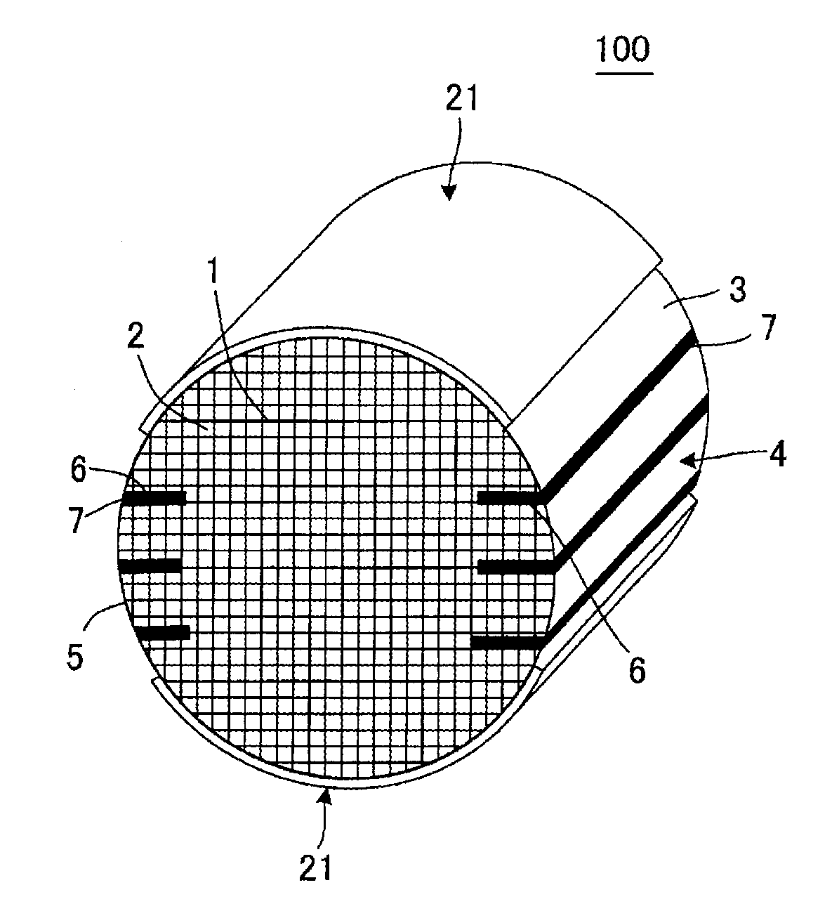
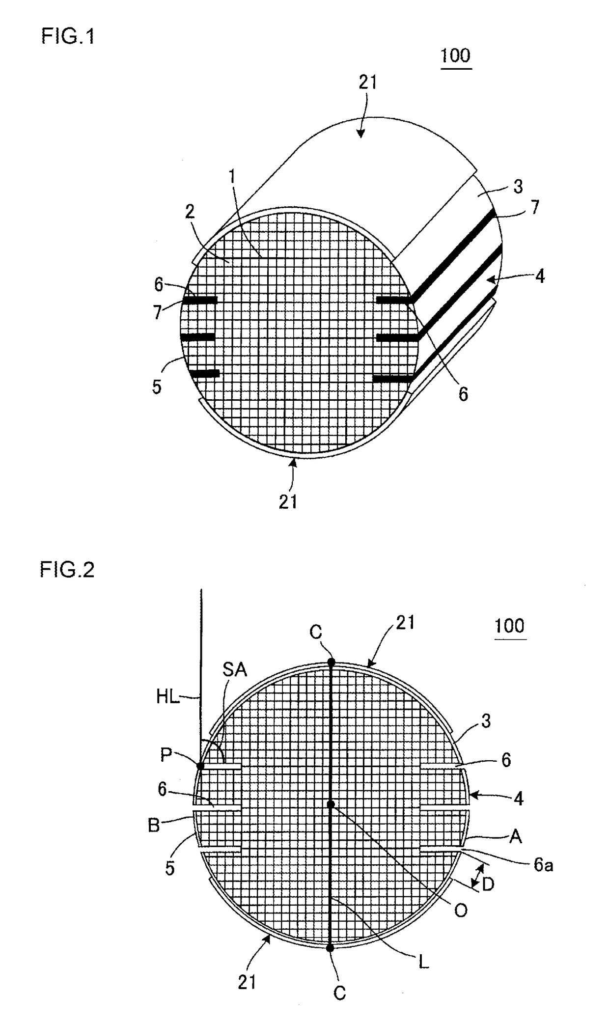
[0018]The present invention has been developed in view of the abovementioned problems. According to the present invention, there is provided a honeycomb structure which is a catalyst carrier and also functions as a heater when a voltage is applied thereto, and which can inhibit an unevenness of a temperature distribution when the voltage is applied thereto and can improve a thermal shock resistance.
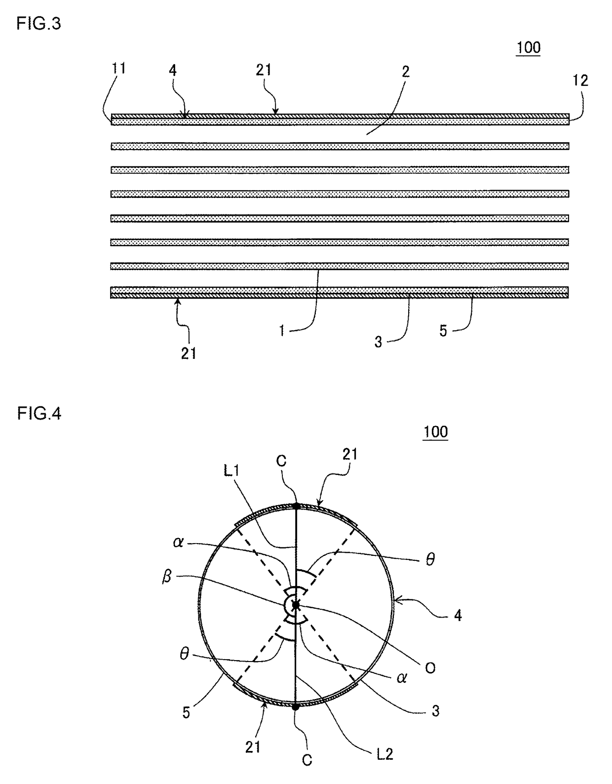
[0031]In a honeycomb structure of the present invention, one or more slits opened in a side surface are formed in a honeycomb structure body. Furthermore, in the slits formed in the honeycomb structure body, a charging material containing a plurality of aggregate particles and a neck material entering into spaces among the aggregate particles to bond the aggregate particles to one another is disposed. Additionally, in the honeycomb structure of the present invention, a ratio (α2 / α1) of a thermal expansion coefficient α2 of the charging material to a thermal expansion coefficient α1 of the honeycomb structure body is from 0.6 to 1.5. Therefore, the honeycomb structure of the present invention is a catalyst carrier and also functions as a heater when a voltage is applied thereto, and can inhibit an unevenness of a temperature distribution when the voltage is applied thereto and can improve a thermal shock resistance.

Problems solved by technology

However, in the heater made of the metal, an electric resistance is low, which has caused the problem that a current excessively flows through the heater and damages a power source circuit sometimes when such a power source of the high voltage is used.
The first problem is that, for example, when the charging material excessively thermally expands, a shearing stress is generated in a boundary between the honeycomb structure body and the charging material and the charging material is damaged sometimes. The second problem is that, for example, when a strength of the charging material is low, the charging material is easily broken and the slits are noticeably deformed to generate cracks and the like from the vicinities of the slits to end faces of the honeycomb structure body sometimes. The third problem is that, for example, when Young's modulus of the charging material is excessively high, a stress relaxing ability by the slits deteriorates and cracks and the like are generated in, for example, the end faces of the honeycomb structure body sometimes.

Method used


Image

  • Honeycomb structure
  • Honeycomb structure
  • Honeycomb structure

Examples


example 1

[0133]Silicon carbide (SiC) powder and metal silicon (Si) powder were mixed at a mass ratio of 80:20 to prepare a silicon carbide-metal silicon mixture. Then, to the silicon carbide-metal silicon mixture, hydroxypropyl methylcellulose as a binder and a water absorbable resin as a pore former were added and water was also added to obtain a forming raw material, and the forming raw material was kneaded by using a vacuum pugmill to prepare a columnar kneaded material. A content of the binder was 7 parts by mass, when a total of the silicon carbide (SiC) powder and the metal silicon (Si) powder was 100 parts by mass. A content of the pore former was 3 parts by mass, when the total of the silicon carbide (SiC) powder and the metal silicon (Si) powder was 100 parts by mass. A content of the water was 42 parts by mass, when the total of the silicon carbide (Sic) powder and the metal silicon (Si) powder was 100 parts by mass. An average particle diameter of the silicon carbide powder was 20...


PUM

PropertyMeasurementUnit
Young's modulusaaaaaaaaaa
porosityaaaaaaaaaa

Abstract

The honeycomb structure includes a honeycomb structure body and a pair of electrode members disposed on a side surface of the honeycomb structure body, each of the pair of electrode members is shaped in the form of a band extending in a cell extending direction, and in a cross section perpendicular to the extending direction of cells, one electrode member is disposed on a side opposite to the other electrode member via a center of the honeycomb structure body, one or more slits opened in the side surface are formed in the honeycomb structure body, the honeycomb structure body has a charging material charged into the at least one slit, the charging material contains aggregates and a neck material, and a ratio (α2 / α1) of a thermal expansion coefficient α2 of the charging material to a thermal expansion coefficient α1 of the honeycomb structure body is from 0.6 to 1.5.

Description

[0001]The present application is an application based on JP 2014-050842 filed on Mar. 13, 2014 with Japan Patent Office, the entire contents of which are incorporated herein by reference.BACKGROUND OF THE INVENTION[0002]Field of the Invention[0003]The present invention relates to a honeycomb structure, and more particularly, it relates to a honeycomb structure which is a catalyst carrier and also functions as a heater when a voltage is applied thereto, and which can inhibit an unevenness of a temperature distribution when the voltage is applied thereto and can improve a thermal shock resistance.[0004]Background Art[0005]Heretofore, a honeycomb structure which is made of cordierite and onto which a catalyst is loaded has been used in treatment of harmful substances in an exhaust gas discharged from a car engine. Furthermore, it is also known that a honeycomb structure formed by a silicon carbide sintered body is for use in purification of the exhaust gas (e.g., see Patent Document 1)...

Claims


Application Information

Patent Timeline
Patent Type & Authority Patents(United States)
IPC IPC(8): B01D50/00F01N3/022B01J35/04B01D46/24C04B35/195F01N3/28F01N3/20C04B38/00C04B111/32
CPCF01N3/0222B01D46/2429B01J35/04C04B35/195C04B38/0006F01N3/2026F01N3/2828B01D46/2418Y02T10/26C04B2111/32C04B2235/3418C04B2235/3826C04B2235/428C04B2235/5427C04B2235/5436C04B2235/6021F01N2260/10F01N2330/06F01N2330/14F01N2330/30C04B35/565C04B2111/00793C04B2111/0081Y02T10/12B01D46/24494B01D46/2476B01D46/24495C04B38/067B01D46/2425B01D46/24491
Inventor HOSOI, YUSUKEWATANABE, TSUYOSHIINOUE, TAKAYUKI
Owner NGK INSULATORS LTD
Learn More