
Measuring device

a technology of measuring device and measuring chamber, which is applied in the direction of measurement device, scientific instruments, instruments, etc., can solve the problems of unable to measure, dissolved oxygen analyzer consumption of electrolytic solution, and measurement of kind of measuring device, etc., and achieves wide measurement range, high accuracy without sacrificing responsiveness, and high responsiveness.

Active Publication Date: 2017-11-28
HORIBA ADVANCED TECHNO
View PDF12 Cites 0 Cited by
  • Summary
  • Abstract
  • Description
  • Claims
  • Application Information

AI Technical Summary

Benefits of technology

The invention allows for accurate and efficient measurement of low or high concentrations of substances in a sample without sacrificing responsiveness over a wide range. This is achieved by using a guard electrode that can be activated at different concentrations of the substance to prevent unwanted consumption of the electrolytic solution and extend the life span of the solution. This is particularly useful in manufacturing semiconductors where continuous operation is common and the frequency of solution replacement is high.

Problems solved by technology

A problem that is common to this kind of measuring devices such as the dissolved oxygen analyzer is consumption of an electrolytic solution.
The electrolytic solution into which a pair of the electrodes (an anode and a cathode) are immersed is consumed because of an electrochemical reaction on the electrodes at a time of the measurement and eventually the measurement becomes impossible.
As a result of this, it is not possible to secure the measurement accuracy until the existing oxygen is completely reduced so that there is a problem that the responsiveness is aggravated.
However, with this arrangement, in case that the oxygen concentration is high, the reaction amount of the oxygen in the measuring sample reduced on the guard electrode increases so that there is a problem that the electrolytic solution is quickly consumed.
As a result of this, the electrolytic solution is heavily consumed.
This problem is common to not only the dissolved oxygen analyzer but also a measuring device that reduces the object substance such as oxygen that enters from the measuring sample through a permeable member by the use of the cathode that is immersed in the electrolytic solution or that oxidizes the object substance by the use of the anode that is immersed in the electrolytic solution, and that measures a concentration of the object substance in the measuring sample based on an value of an electric current that flows between the anode and the cathode at a time of reduction or oxidization.

Method used


Image

  • Measuring device
  • Measuring device
  • Measuring device

Examples


Embodiment Construction

[0028]One embodiment of this invention will be explained with reference to drawings.

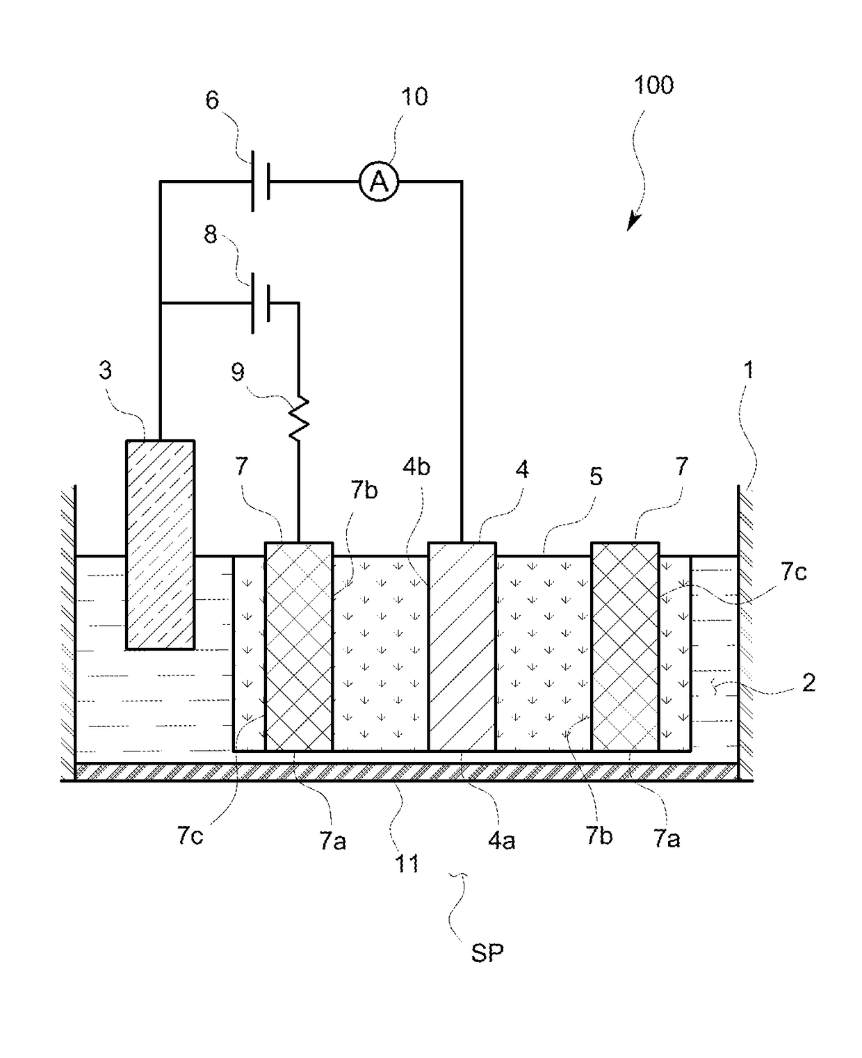
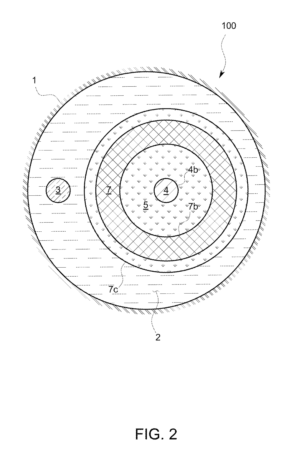
[0029]A dissolved oxygen analyzer 100 as being a measuring device in accordance with this embodiment is to measure oxygen in a hydrofluoric acid solution flowing in a hydrofluoric acid line of, for example, a semiconductor manufacturing equipment, and as shown in FIG. 1 and FIG. 2, comprises a casing 1 provided with an oxygen permeable membrane 11 as being a permeable member at a distal end of the casing 1, a cathode 4 and an anode 3 as being a pair of electrodes, namely, a first electrode and a second electrode that are immersed into an electrolytic solution 2 in the casing 1. The dissolved oxygen analyzer 100 measures a concentration of oxygen in a measurement sample (SP) by reducing oxygen in the measurement sample (SP) entering inside of the dissolved oxygen analyzer 100 from the outside of the dissolved oxygen analyzer 100 through the oxygen permeable membrane 11 by the use of the cathode 4 as b...


PUM

PropertyMeasurementUnit
resistanceaaaaaaaaaa
electric currentaaaaaaaaaa
resistanceaaaaaaaaaa

Abstract

A measuring device comprises a guard electrode that is arranged around a cathode, reduces oxygen that is not from an oxygen permeable membrane, and inhibits the oxygen from reaching the cathode. The guard electrode is electrically connected to an anode through a resistor having a prescribed resistance.

Description

FIELD OF THE ART[0001]This invention relates to a measuring device such as a dissolved oxygen analyzer that reduces or oxidizes an object substance such as oxygen or the like that enters from a measurement sample by permeating through a permeable member by the use of one of a pair of electrodes that are immersed in an electrolytic solution and that measures a concentration of the object substance in the measurement sample based on a value of an electric current that flows between the above-mentioned a pair of electrodes at a time when the object substance is reduced or oxidized.BACKGROUND ART[0002]A problem that is common to this kind of measuring devices such as the dissolved oxygen analyzer is consumption of an electrolytic solution. The electrolytic solution into which a pair of the electrodes (an anode and a cathode) are immersed is consumed because of an electrochemical reaction on the electrodes at a time of the measurement and eventually the measurement becomes impossible. As...

Claims


Application Information

Patent Timeline
Patent Type & Authority Patents(United States)
IPC IPC(8): G01N27/404
CPCG01N27/404
Inventor SUZUKI, RIICHIROINOUE, KENTARO
Owner HORIBA ADVANCED TECHNO
Learn More