Heat dissipating structure

a technology of heat dissipation structure and heat dissipation heat, which is applied in the direction of dielectric characteristics, non-printed electric components association, non-metallic protective coating application, etc., can solve the problems of additional modification work, significant increase in heat generation, damage to electronic components, etc., to prevent overheating of electronic components, prevent deterioration of electronic components performance, and dissipate heat

Active Publication Date: 2017-11-21
KANEKA CORP
View PDF43 Cites 3 Cited by
  • Summary
  • Abstract
  • Description
  • Claims
  • Application Information

AI Technical Summary

Benefits of technology

[0021]The heat dissipation structure of the present invention can dissipate heat generated by electronic components placed on both sides of a printed circuit board, through a cured product of a thermally conductive curable liquid resin composition placed on the second surface, to control the thermal conduction direction, prevent overheating of the electronic components on the first surface, and prevent deterioration of the performance of the electronic components.

Problems solved by technology

The improvement in the performance of arithmetic elements and light-emitting elements has been accompanied by a significant increase in the amount of heat generation, which may cause malfunctions in electronic devices and lighting and display devices or cause damage to electronic components.
This poses the important challenge of how to dissipate heat from such elements.
A problem associated with the use of molded products is that additional work is required to modify the mold and the like for each component.
On such printed circuit boards as described above, electronic components of various sizes from small to large are used, and therefore the heat dissipation components such as heat-dissipating sheets cannot conform to the fine irregularities.
This reduction in contact area problematically causes a reduction in the efficiency of heat transfer from the heat-generating element to the heat-dissipating element, which does not allow the heat dissipation components to sufficiently exhibit their heat dissipation properties.
In addition, since the resin applied to the front and back surfaces of the printed circuit board transfers heat to all directions, the direction for heat dissipation cannot be controlled.
The heat is therefore conducted to portions that come into contact with the human body during the use of the electronic device, which leads to the risk of burn injuries during the use.
However, since this technique requires multiple substrates, it is difficult to make a space in the electronic devices desired to be miniaturized and reduced in thickness, and the design of these devices is also required to be greatly changed.

Method used


Image

  • Heat dissipating structure
  • Heat dissipating structure
  • Heat dissipating structure

Examples


examples

[0087]The embodiments and effects of the present invention will be explained below with reference to examples which, however, are not intended to limit the scope of the present invention.

(Viscosity of thermally conductive curable liquid resin composition)

[0088]The viscosity of thermally conductive curable liquid resin compositions was measured at 23° C. and 50% RH with a BH viscometer at 2 rpm.

(Thermal conductivity of thermally conductive curable liquid resin composition)

[0089]The thermally conductive curable liquid resin compositions were wrapped in Saran Wrap (registered trademark) and then measured for thermal conductivity at 23° C. using a hot disk thermal conductivity meter (TPA-501 available from Kyoto Electronics Manufacturing Co., Ltd.) by sandwiching a sensor (size: 4φ) between two specimens.

(Tensile elastic modulus of cured product of thermally Conductive Curable Liquid Resin Composition)

[0090]The tensile elastic modulus of mini dumbbell specimens prepared by curing the th...

examples 1 and 2

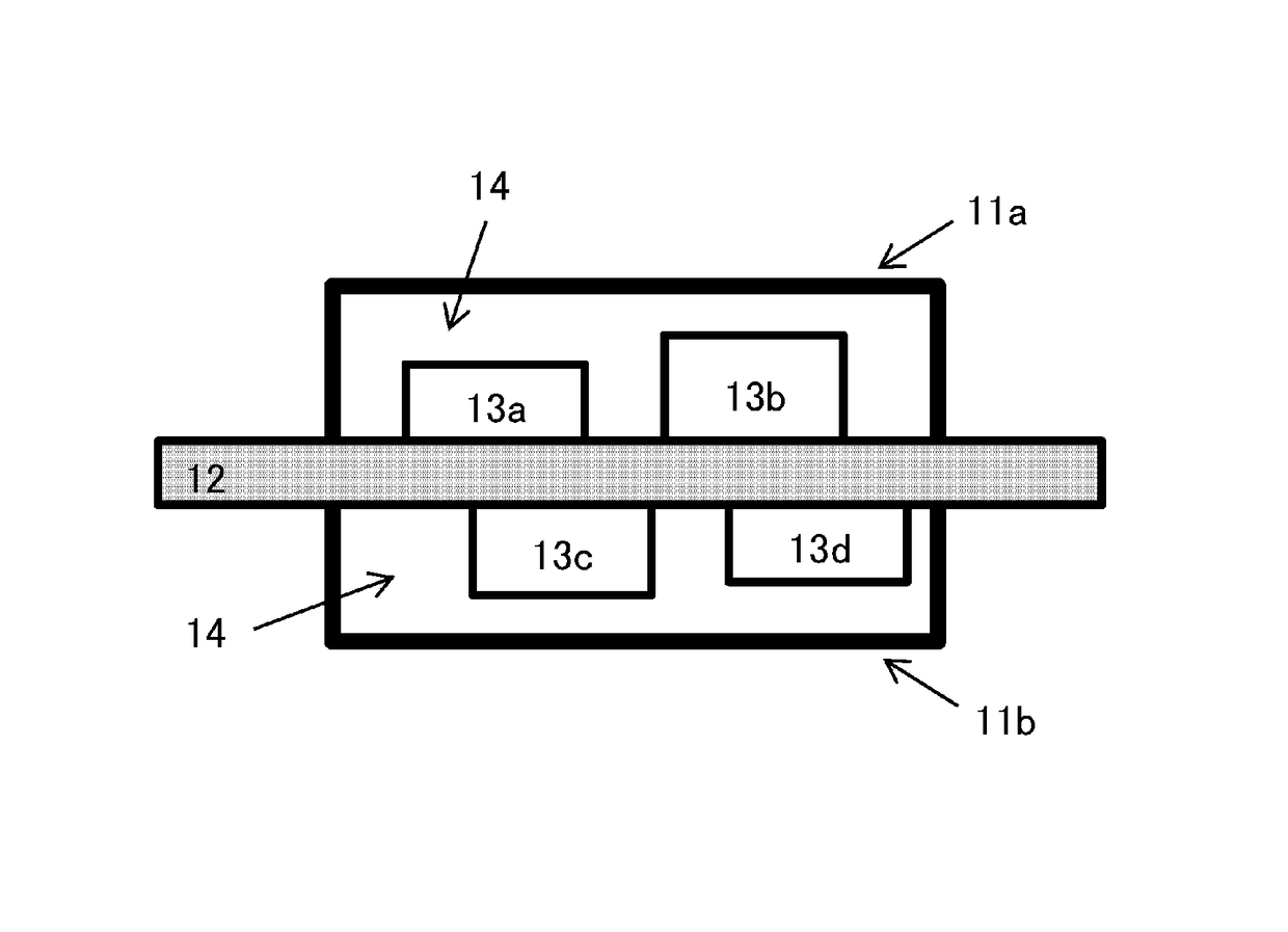
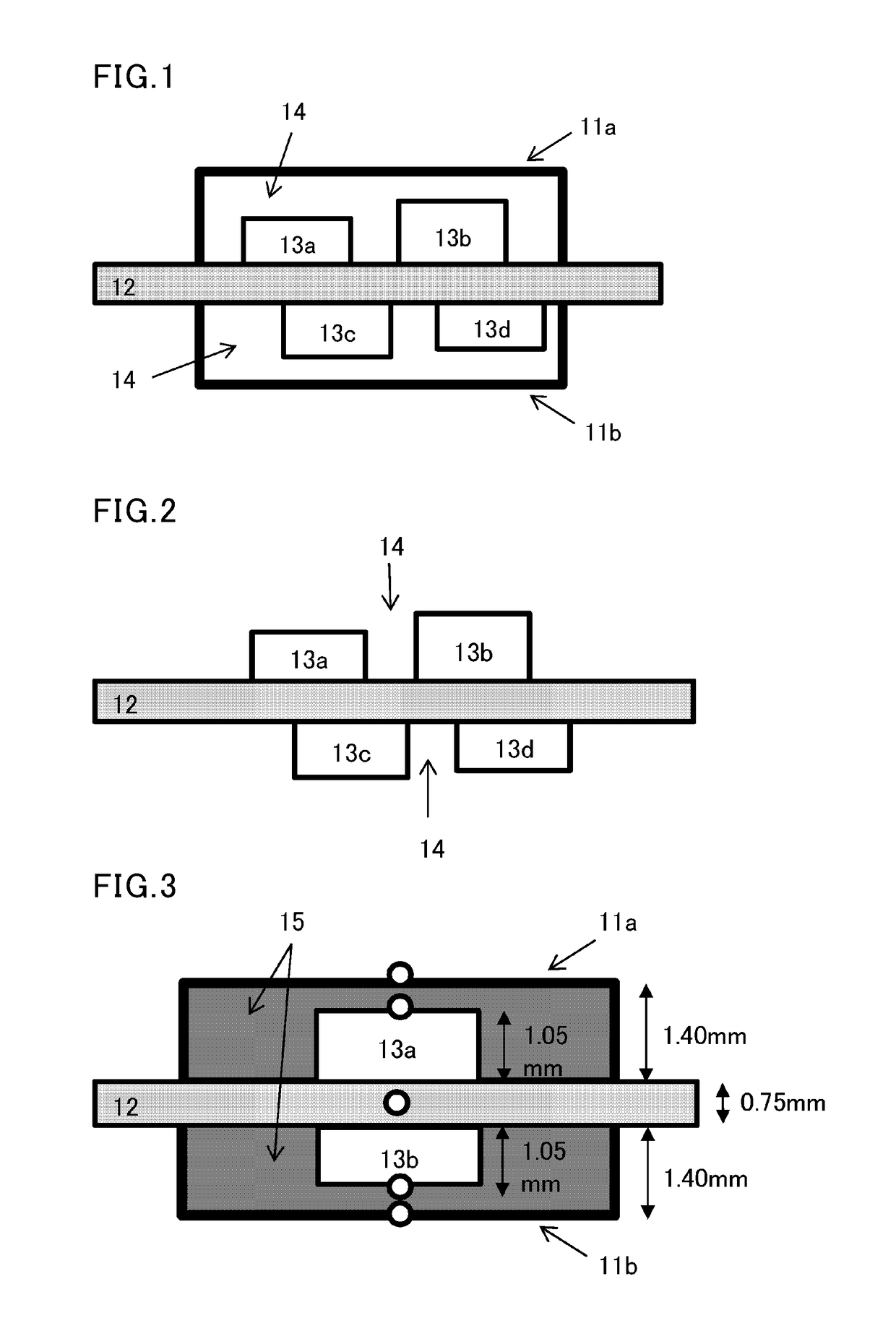
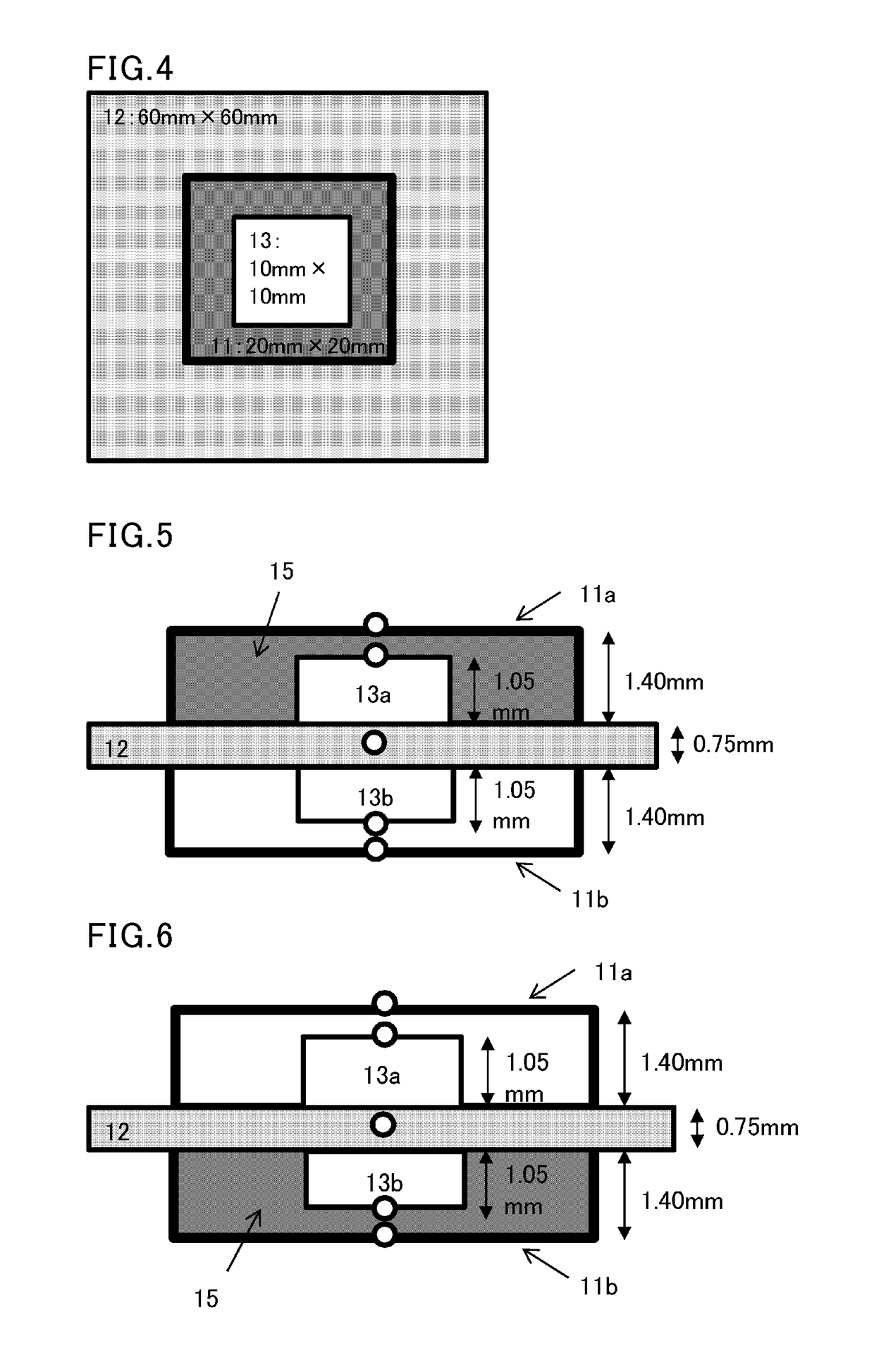
[0107]The resin (I-1) obtained in Synthesis 1 (90 parts by weight), the resin (I-2) obtained in Synthesis 2 (10 parts by weight), a plasticizer (Monocizer W-7010 available from DIC; 100 parts by weight), an antioxidant (Irganox 1010; 1 part by weight), and thermally conductive fillers (450 parts by weight aluminum hydroxide, and 100 parts by weight zinc oxide) were sufficiently stirred and kneaded by hand. Then the mixture was dehydrated in vacuo while being kneaded under heat with a 5-L butterfly mixer. After completion of the dehydration, the mixture was cooled and mixed with a dehydrating agent (A171; 2 parts by weight) and curing catalysts (tin neodecanoate and neodecanoic acid; 4 parts by weight each). Thus, a thermally conductive curable liquid resin composition was obtained. After the obtained thermally conductive curable liquid resin composition was measured for viscosity and thermal conductivity, the thermally conductive curable liquid resin composition was filled as shown ...

examples 3 and 4

[0112]The evaluation procedure described in Examples 1 and 2 was followed but using a thermally conductive curable silicone resin composition (KE-4918 available from Shin-Etsu Chemical Co., Ltd., paste form, moisture-curable composition, thermal conductivity: 0.9 W / (m·K)) in place of the thermally conductive curable liquid resin composition used in Examples 1 and 2. The evaluation results are shown in Table 1.

[0113]

TABLE 1Examples / Comparative ExamplesComparativeComparativeComparativeComparativeComparativeExample 1Example 1Example 2Example 3Example 2Example 4Example 5Example 3Example 4AmountElectronic1.01.01.01.01.01.01.01.01.0of heatcomponentgeneration13a(W)Electronic0.20.20.20.20.90.90.90.20.9component13bFillingElectromagneticNot filledNot filledFilledFilledNot filledNot filledFilledNot filledNot filledshieldingcase 11aElectromagneticFilledNot filledFilledNot filledFilledNot filledFilledFilledFilledshieldingcase 11bMeasuredElectromagnetic50.450.854.456.454.155.768.150.654.4tem-shie...


PUM


Abstract

A heat dissipation structure including: a printed circuit board; a first heat-generating element; a second heat-generating element; and a cured product of a thermally conductive curable liquid resin composition, the printed circuit board having a first surface and a second surface that is opposite to the first surface, the first heat-generating element being placed on the first surface, the second heat-generating element being placed on the second surface, the first heat-generating element generating an equal or greater amount of heat than the second heat-generating element, the second heat-generating element being surrounded by the cured product, the first heat-generating element being surrounded by a layer that has a lower thermal conductivity than the cured product.

Description

[0001]This is the U.S. national stage of application No. PCT / JP2013 / 083338, filed on Dec. 12, 2013. Priority under 35 U.S.C. §119(a) and 35 U.S.C. §365(b) is claimed from Japanese Application No. 2013-108198, filed May 22, 2013, the disclosure of which is also incorporated herein by reference.TECHNICAL FIELD[0002]The present invention relates to a heat dissipation structure for use in electronic devices, precision apparatuses, or the like.BACKGROUND ART[0003]Electronic devices (e.g. PCs, cellphones, PDAs), lighting and display devices (e.g. LED, EL) and the like have recently made a significant improvement in performance. This improvement is attributed to a significant improvement in the performance of arithmetic elements and light-emitting elements. The improvement in the performance of arithmetic elements and light-emitting elements has been accompanied by a significant increase in the amount of heat generation, which may cause malfunctions in electronic devices and lighting and d...

Claims


Application Information

Patent Timeline
Patent Type & Authority Patents(United States)
IPC IPC(8): H05K7/20H01L23/29H05K1/02H01L23/373H05K1/18H05K3/28H01L23/31
CPCH05K1/0209H01L23/295H01L23/3737H05K1/18H05K3/284H01L23/3121H01L2924/0002H05K2203/1327H05K2201/0104H05K2201/06H05K2201/10371H05K2201/10545H01L2924/00
Inventor KOUKAMI, AKIHAGIWARA, KAZUOOGUMA, KEISUKEFUJIMOTO, KAZUHIDE
Owner KANEKA CORP
Why Eureka
Try Eureka