Eureka AIR delivers breakthrough ideas for toughest innovation challenges, trusted by R&D personnel around the world.

Borehole while drilling electromagnetic tomography advanced detection apparatus and method

a detection apparatus and technology of electromagnetic tomography, applied in the field of drilling technology, can solve the problems of affecting the normal production of tunnels and roadways, and longer construction period, so as to reduce the number of drilling boreholes, improve the detection accuracy of geophysical prospecting, and advance and accurate detection of roadways in driving.

Inactive Publication Date: 2017-11-14
WUHAN CONOURISH COALMINE SAFETY TECH
View PDF2 Cites 0 Cited by
  • Summary
  • Abstract
  • Description
  • Claims
  • Application Information

AI Technical Summary

Benefits of technology

[0007]The object of the present invention is to provide an advanced detection apparatus and method by borehole while-drilling electromagnetic tomography, by which the borehole being drilled in the head direction of tunnel, roadway and working face driving can be detected, and the harmful geological formations such as water-rich bodies and water-conducting channels within the range of 0˜50 m around the borehole can be detected, and an accuracy and effective predetection can be achieved.
[0017]Step 7: According to the apparent resistivity spectrum of the surrounding rock in the borehole and the track map of the borehole obtained from Step 6 to calculate the 3 times standard derivation value and the average value of the apparent resistivity at all measuring points of the borehole, if the difference between the average value and the apparent resistivity value at each measuring point of the borehole is more than the 3 times standard derivation value, then there is a abnormal low-resistivity body within the range of 0.5˜50 m distance from the measuring point and whether the low-resistivity body is a water-rich body or not can be analyzed based on the results of abnormal low-resistivity and geological data surrounding the borehole by the prior method disclosed in the reference “The Principle of Electromagnetic Sounding”, so that the advanced detection of borehole while drilling can be achieved.
[0019]1) According to the present invention, the probe is mounted in the borehole being drilled between the drilling stem and bit of the rig and screwed connecting to them, and the probe can transmit a set of electromagnetic waves having different frequencies to detect geological characteristics of rock surrounding the borehole within different radius distance, to judge the presence or absence of harmful geological bodies such as water-rich bodies within a certain range around the borehole. With the borehole drilling, the probe will automatically detect at different depth to obtain the geological characteristics within a cylinder surrounding the whole borehole, so as to achieve a larger detection range, more information, and accurate and reliable since the detected results at adjacent measuring points can be verified with each other. Further, the present invention can greatly reduce the number of the detecting pipes to save time and costs, improve work efficiency, and improve the ability to exclude the potential flooding in tunnel driving of coal mine.
[0020]2) According to the present invention, a set of different frequencies of electromagnetic waves are transmitted to obtain a large amount of data, and the underground artificial strong interference background (since simple wall rock surrounding the borehole, absence of drilling machine, rail track, I-beam support, bolts support, transport belt brackets and other metal facilities) can be avoided to achieve a relatively fixed background, so that the ability to identify and process weak signals can be improved to ensure that the results are accurate and reliable as a guide to provide a more scientific basis for roadway excavation.
[0021]3) According to the present invention, the detection results can be displayed real-time by the site host when detection, automatically analyzed into a diagram for forecasting without complicated manual data analysis and processing stages, so that a reliable forecast data can be provided for the geological detecting staff Thus, the apparatus of the present invention has the advantages of operability, effectiveness and practicality.
[0023]The present invention achieves the advanced detection while drilling by roadway advanced drilling, a close-range and fine scanning detection can be achieved within a radius of 0.5˜50 m around the borehole. It is a combination of drilling and geophysical exploration, so that it cannot only improve the detection accuracy of geophysical prospecting, but also reduce the number of drilling boreholes to achieve the advanced and accurate detection of roadway in driving.

Problems solved by technology

Although the drilling method can obtain quite reliable drilling results, the longer construction period and higher costs will affect the normal production of the tunnel and roadway.
However, for those prior art methods, there are obvious interference of roadway and working face, for example, the detecting results of three-pole method and mine transient electromagnetic method can be affected seriously by the metal apparatus in the roadway and tunnel such as boring machine, rail track, I-beam support, bolts support, transport belt brackets.
In addition, the construction design on the site, data observations and the results of the analysis are complex, and it is difficult for overcome the problem of multiple solutions due to using single detecting parameter—resistivity.
If using a combination of above-mentioned methods, the costs for advanced forecast will be greatly increased.
Furthermore, a disadvantage of those borehole detecting methods after drilled is that the detection of borehole usually cannot be achieved because the borehole often collapses after drilling due to relatively soft coal seam.
The seismic method is mainly to solve the problem of geological tectonic interface and cannot explain the rich-water configuration.

Method used


Image

  • Borehole while drilling electromagnetic tomography advanced detection apparatus and method
  • Borehole while drilling electromagnetic tomography advanced detection apparatus and method
  • Borehole while drilling electromagnetic tomography advanced detection apparatus and method

Examples


Embodiment Construction

[0029]The invention will be further described in detail in combination with the accompanying drawings.

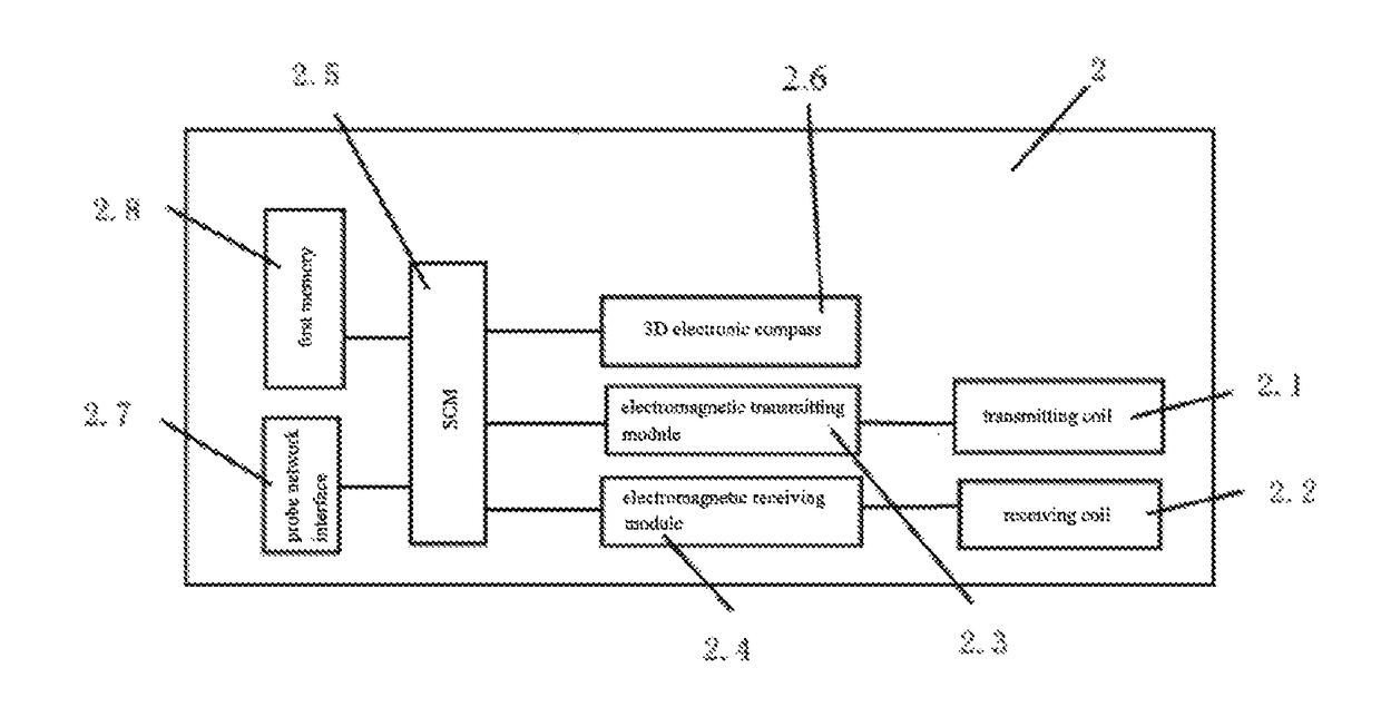
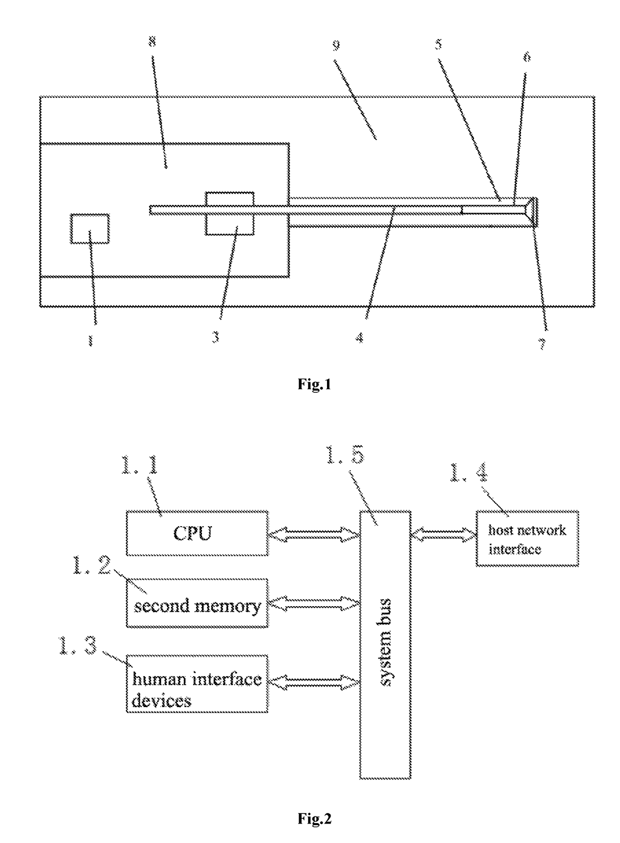
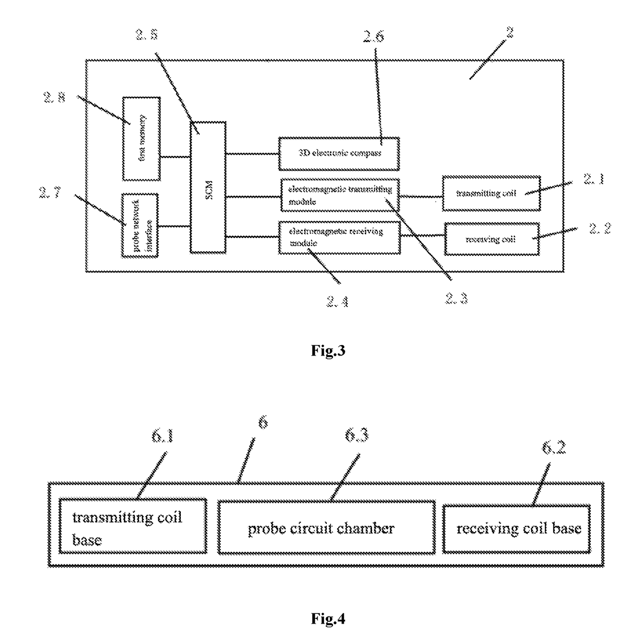
[0030]A borehole while-drilling electromagnetic tomography advanced detection apparatus as shown in FIGS. 1-4 comprises a site host 1, a drilling rig 3, a detecting pipe 6 screwed coupling on one end to a drilling stem 4 of the drilling rig 3, a drilling bit 7 screwed coupling to the other end of the detecting pipe 6, wherein the detecting pipe 6 is provided with a probe 2 comprising a transmitting coil 2.1, a receiving coil 2.2, an electromagnetic transmitting module 2.3, an electromagnetic receiving module 2.4, a SCM (Single Chip Microcomputer) 2.5, a 3D electronic compass 2.6, a network interface of the probe 2.7 and a first memory 2.8, in which the memory port of the SCM 2.5 is connected to the first memory 2.8, the communication port of the SCM 2.5 is connected to the network interface of the probe 2.7, the compass communication port of the SCM 2.5 is connected to the communica...


PUM


Abstract

A borehole while-drilling electromagnetic tomography advanced detection apparatus includes a site host, a drilling rig, a detecting pipe screwed coupling on one end to a drilling stem of the drilling rig, a drilling bit screwed coupling to the other end of the detecting pipe, wherein the detecting pipe is provided with a probe comprising a transmitting coil, a receiving coil, an electromagnetic transmitting module, an electromagnetic receiving module, a SCM (Single Chip Microcomputer), a 3D electronic compass, a network interface of the probe and a first memory, in which the memory port of the SCM is connected to the first memory, and the network interface of the probe can be data-communicated with the site host.

Description

FIELD OF THE INVENTION[0001]The present invention relates to the field of drilling technology, in particular to an advanced detection apparatus and method by using borehole while drilling electromagnetic tomography technology.BACKGROUND[0002]The advanced detection primarily means to detect the presence or absence of harmful geological formations or water-rich bodies and water-conducting channels in the head direction of tunnel, roadway and working face driving by direct or indirect way, so as to provide detailed detection information for security of tunnel driving.[0003]The direct method currently used for coal mine advanced detection is drilling method and the indirect method is geophysical prospecting method. Although the drilling method can obtain quite reliable drilling results, the longer construction period and higher costs will affect the normal production of the tunnel and roadway.[0004]The geophysical prospecting methods available for advanced detection now are three-pole m...

Claims


Application Information

Patent Timeline
Patent Type & Authority Patents(United States)
IPC IPC(8): G01V3/30G01R33/00
CPCG01V3/30Y02A90/30
Inventor WU, QIANGLIU, LIULI, HENGYUANZENG, YIFANTAO, FENGJUANXIE, SHUIQINGLIU, CHUNSHENG
Owner WUHAN CONOURISH COALMINE SAFETY TECH
Why Eureka
Eureka Blog
Learn More