Bracket and method of using same

a technology of mounting brackets and brackets, which is applied in the direction of mechanical devices, machine supports, fastening means, etc., can solve the problems of not allowing such variations, tampering with existing products, and requiring a lot of time and effort to secure fencing wires to fence posts, etc., to achieve the effect of reducing or eliminating movemen

Active Publication Date: 2017-11-14
GALLAGHER ELECTRONICS LTD CO
View PDF6 Cites 0 Cited by
  • Summary
  • Abstract
  • Description
  • Claims
  • Application Information

AI Technical Summary

Benefits of technology

[0067]The low clearance between the bracket and fence posts minimises or eliminates movement between them.
[0077]provides a rigid and secure connection between the bracket and structures due to the large surface area engagement that supports higher compressive loading;
[0078]provides a rigid and secure connection between the bracket and structures due to the large shear area engagement that supports higher axial tensile loads;

Problems solved by technology

However, there are a number of common problems associated with these products.
Firstly, it can be tedious and time consuming to secure fencing wire to the fencing posts due to the mechanism and structure of existing connectors and brackets.
Secondly, in many cases the fencing wire has to be connected at various different angles to the posts.
Many existing products do not allow for such variations in the angle of connection between the fence wires and the posts.
Thirdly, many existing products are not tamper-proof.
Connectors or brackets can be easily tampered with by people or animals either deliberately or accidentally, which can be a particular issue when the fence is being used for security reasons.
Deliberate or inadvertent tampering may create a loose connection between the fencing wire and the posts.

Method used


Image

  • Bracket and method of using same
  • Bracket and method of using same
  • Bracket and method of using same

Examples


Embodiment Construction

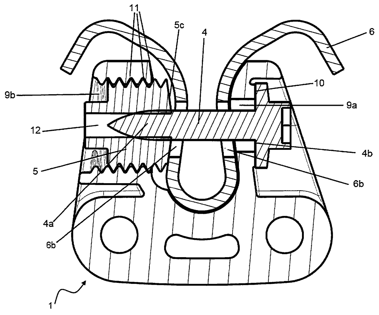
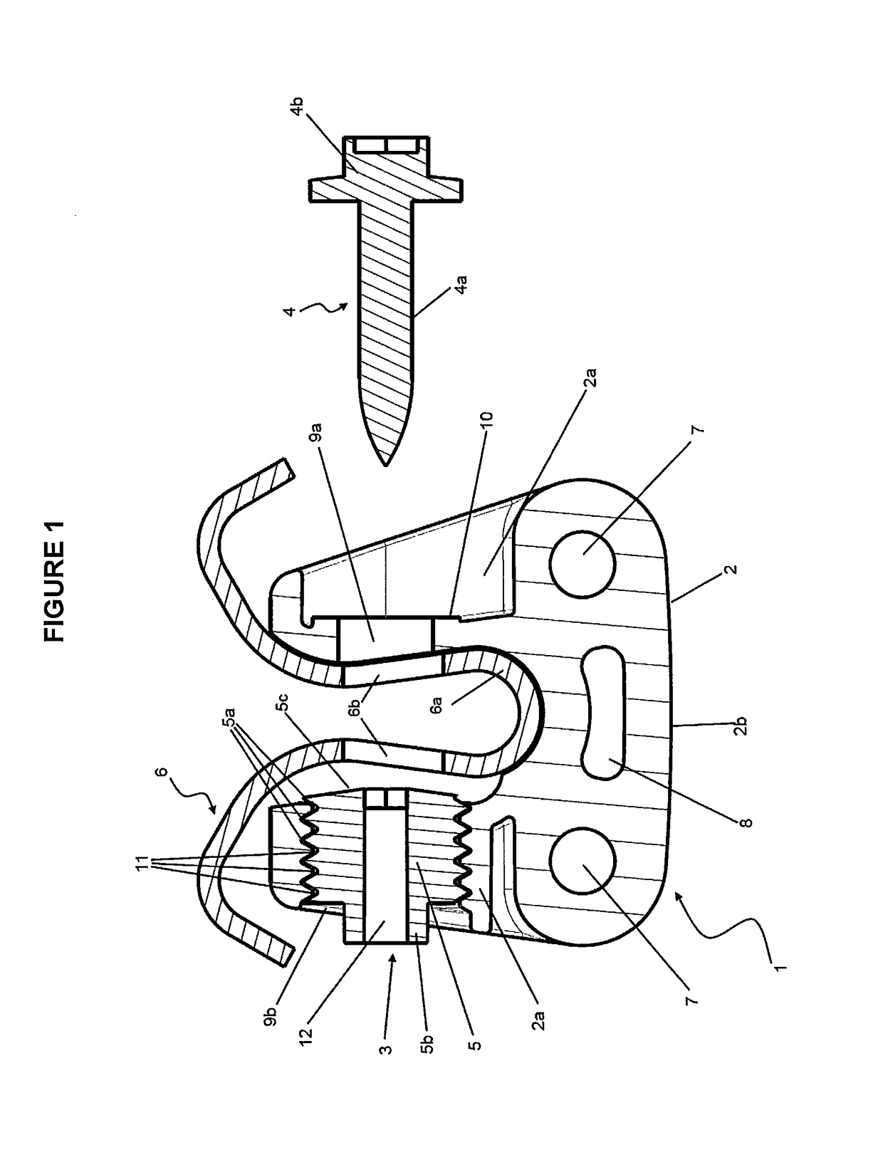
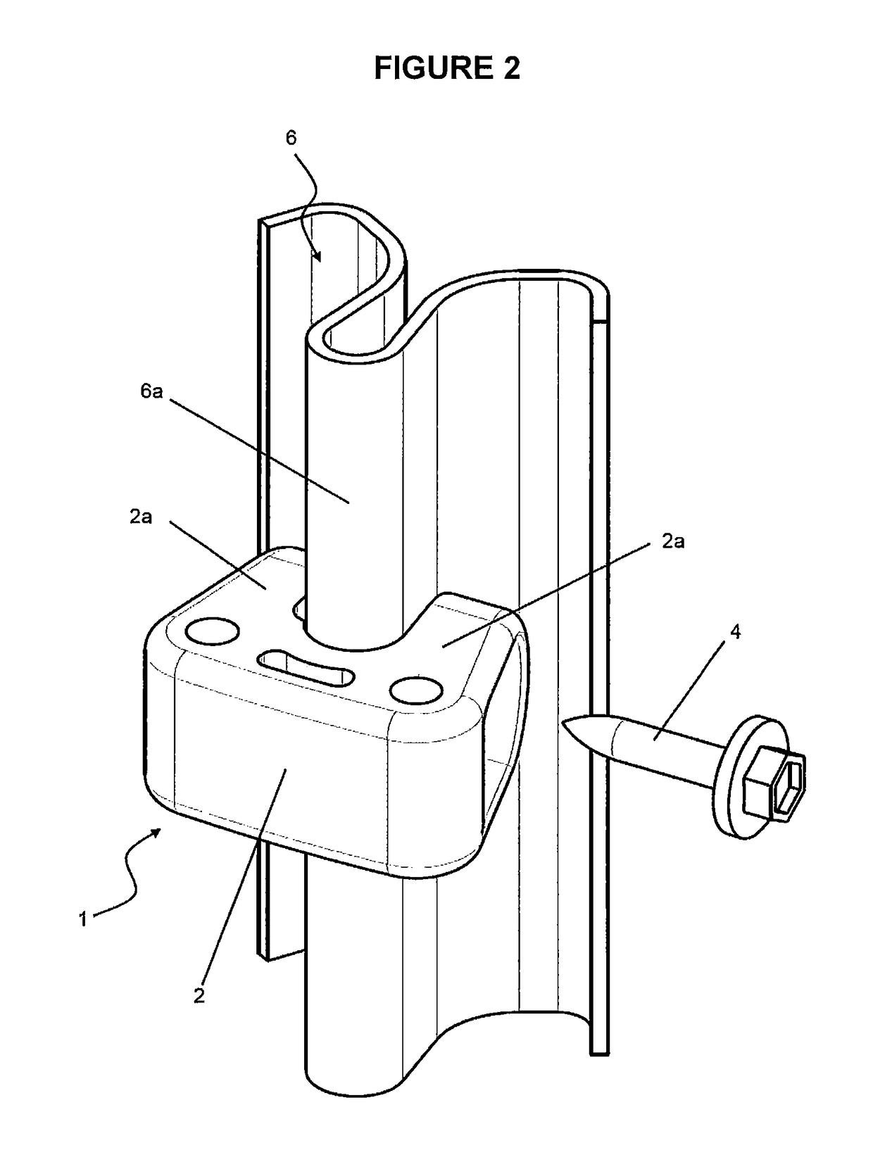
[0087]The mounting bracket of the present invention (generally indicated by arrow 1) is depicted in FIG. 1 and consists of a body (2) and a securing mechanism (3) in the form of a first fastener (4) and a second fastener (5).

[0088]The body (2), formed from plastics material, has a pair of opposing arms (2a) arising from a base (2b) to form a substantially U-shaped open recess. The open recess is intended to engage with a fence post (6) or the like. The fence post includes a portion (6a) substantially complementary to the open recess and apertures (6b) passing through the portion.

[0089]The body (2) includes recesses and channels (7) that are dimensioned for use with a pin or similar fasteners to allow attachments, such as fence strainers or the like (not shown), to be mounted to the bracket (1). The invention allows those accessories to be easily integrated into a fencing system.

[0090]The bracket (1) is formed using conventional plastic moulding techniques. Some embodiments of the bo...


PUM


Abstract

This invention relates to a mounting bracket including a body configured to engage with at least a part of a structure, the body includes an aperture for a fastener; a securing mechanism to secure the bracket to the structure; the securing mechanism includes a first and second fastener, the fasteners configured to engage with each other, the second fastener also engages with a second aperture of the body, the second fastener and second aperture includes a complementary guide and track in the form of a co-operating helical screw thread.

Description

CROSS-REFERENCE TO RELATED APPLICATIONS[0001]This application is the United States National Phase of PCT Patent Application No. PCT / NZ2014 / 000129 filed 26 Jun. 2014, which claims priority to New Zealand Patent Application No. 613316 filed 17 Jul. 2013, each of which is incorporated herein by reference.TECHNICAL FIELD[0002]This invention relates to a mounting bracket and a method of securing the bracket to a post or the like. The invention has particular application to the mounting of fencing wire and / or accessories to posts used in the fencing industry. However, this is not meant to be limiting, and the invention may have applications in other industries.BACKGROUND ART[0003]The use of electric fencing, where an electrical current is applied to a fence line to deliver an electric shock to any objects that come in contact with it, is common in a number of industries. Electric fencing is especially useful for the use of controlling movement of livestock.[0004]Typically, electric fencin...

Claims


Application Information

Patent Timeline
Patent Type & Authority Patents(United States)
IPC IPC(8): F16L3/08A01K3/00E04H17/10F16B2/06F16M13/02
CPCE04H17/10A01K3/00F16M13/02F16B2/065A01K3/005E04H17/124
Inventor MALINS, CRAIG DAVID
Owner GALLAGHER ELECTRONICS LTD CO
Why Eureka
Try Eureka