
Method and apparatus for additive mechanical growth of tubular structures

a technology of mechanical growth and tubular structure, applied in the direction of additive manufacturing process, applying layer means, manufacturing tools, etc., can solve the problems of limited in a few ways, limited in the size and maneuverability of the delivery system, etc., and achieve the effect of adding strength

Inactive Publication Date: 2017-11-07
CONTINUOUS COMPOSITES INC
View PDF69 Cites 5 Cited by
  • Summary
  • Abstract
  • Description
  • Claims
  • Application Information

AI Technical Summary

Benefits of technology

[0006]Enclosed are descriptions for a new method and apparatus for the extrusion of tubular objects. It affords the construction of large-scale objects with a boundless build area, by utilizing the product for support and eliminating the need for an external positioning system.
[0007]Certain embodiments utilize an extrusion method of additive manufacturing. For example, in certain embodiments, an extruder is placed inside a mobile print head that utilizes the cured extruded material as support. The print head may be linked to at least one material source. For example, the linkage between the print head and the at least one material source may be a hose. The length of the hose may allow for greater range of the print head. The hose may range from a few inches to hundreds of feet in length, allowing flexibility in size and applications.
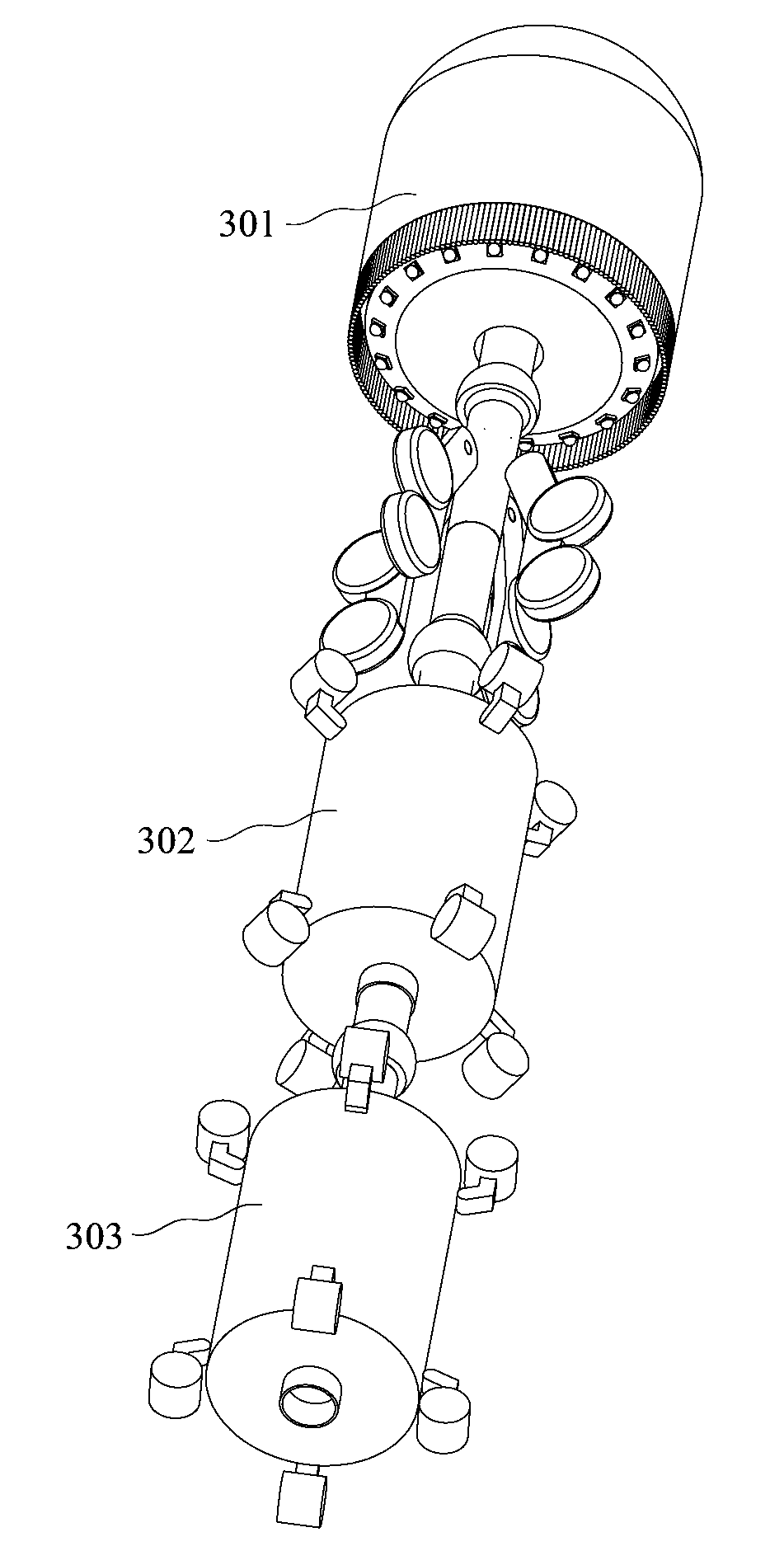
[0011]The print head includes a means of stabilization and propulsion relative to the extrusion tube. Instead of relying on an external means, such as a gantry system or a mechanical arm, the print head utilizes the extrusion tube to provide a foundation for stability and propulsion. Several methods are available, for example, including a motor and a series of wheels that grip the inside of the hardened extrusion tube. The wheels may propel the print head while simultaneously extruding material and creating the extrusion tube.
[0012]The print head may extrude through the one or more nozzles at the same rate, forming a straight extrusion tube. In certain embodiments, however the print head varies the extrusion rate of the nozzles, in order to create, for example, arcs, turns, and complicated objects. The materials extruded may comprise continuous composites, which provide added strength, allowing extrusion tubes to grow into free space opposed to gravity. This affords horizontal, inverted, and complex shaped extrusion tubes.

Problems solved by technology

They are limited in a few ways.
But these are still limited to the size and maneuverability of the system of delivery, the volume under the gantry system or the reach of the mechanical arm.

Method used


Image

  • Method and apparatus for additive mechanical growth of tubular structures
  • Method and apparatus for additive mechanical growth of tubular structures
  • Method and apparatus for additive mechanical growth of tubular structures

Examples


Embodiment Construction

[0028]Enclosed are embodiments for a new method and apparatus for additive manufacturing. See FIG. 1. The basic components of the apparatus may include, for example, a print head 101, a hose 102, and base station 103.

[0029]FIGS. 2A and 2B show an exemplary print head. The perimeter of the print head may comprise one or more individual nozzles 201, which extrude a curable matrix material. The curable matrix materials may reside in reservoirs or spools in the base station. The curable materials may include, for example, composites comprised of a solid strand reinforcement material and a curable liquid matrix material. Uniform curable matrix material without reinforced composites is also envisioned. Each nozzle extrudes the curable matrix material forming an individual path. In composite paths, the solid strand material is completely encased in the curable matrix material and is aligned coaxially with the path. Collectively, extrusions of all paths from the one or more nozzles form a c...


PUM

PropertyMeasurementUnit
diametersaaaaaaaaaa
energyaaaaaaaaaa
propulsionaaaaaaaaaa

Abstract

A method and apparatus is disclosed for additive manufacturing and three-dimensional printing, and specifically for extruding tubular objects. A print head extrudes a curable material into a tubular object, while simultaneously curing the tubular object and utilizing the interior of the cured portion of the tubular object for stabilizing and propelling the print head.

Description

BACKGROUND[0001]Additive manufacturing and 3D printing methods and devices are expanding. Innovations are occurring in materials used, systems of delivery, and applications.[0002]The most popular 3D printers are appliances about the size of a microwave. They are limited in a few ways. Typically, they can only print one material at a time, and the build size is small, less than a cubic foot.[0003]Some additive manufacturing techniques utilize gantry systems or mechanical arms, which afford the ability to build larger objects. But these are still limited to the size and maneuverability of the system of delivery, the volume under the gantry system or the reach of the mechanical arm.[0004]There is a desire to build larger objects utilizing additive manufacturing techniques. A new method and device are needed to build these objects, but also make the objects strong enough to support the increased forces resulting from the larger size.BRIEF SUMMARY OF THE INVENTION[0005]In the following d...

Claims


Application Information

Patent Timeline
Patent Type & Authority Patents(United States)
IPC IPC(8): B29C64/209B29C64/165B29C64/236B29C64/232F16L55/32F16L55/1645B05D7/22F16L55/28B33Y30/00B33Y10/00B29C67/00B29C70/38B29C47/00B29C70/52B05D1/02B05B3/00B05B12/14B29D23/00B05B13/06F16L13/11B29C48/00B29C48/02B29C48/32B29C48/345B29L23/00
CPCB29C64/165B29C47/00B29C47/0002B29C64/209B29C64/232B29C64/236B29C70/382B29C70/388B29C70/522B29C70/524B29C70/525B33Y10/00B33Y30/00F16L55/1645F16L55/28F16L55/32B05D7/222F16L13/11B05B3/001B05B12/1481B05B13/06B05B13/0627B05B13/0636B05D1/02B05D2254/04B29C47/0004B29C70/38B29D23/001B29L2023/00B29C48/00B29C48/02B29C48/022B29C64/118B29C64/112B29C64/241B29C64/268B29C64/393B29C64/40B29C67/24B33Y50/02B33Y70/10B33Y40/20B32B27/308B29C35/0261B29C2035/0827B29C2035/0838B29K2055/02B29L2023/22B33Y40/00
Inventor TYLER, KENNETH
Owner CONTINUOUS COMPOSITES INC
Learn More