Pressure medium container for a hydraulic motor vehicle brake system

a technology for hydraulic motor vehicles and containers, which is applied in the direction of braking systems, functional valve types, braking components, etc., can solve the problems of increasing the complexity and production cost of closing caps, affecting the operation of the braking system, and the flow of pressure medium in the filter pipe. , to achieve the effect of good valve function and less proliferation

Active Publication Date: 2017-10-24
CONTINENTAL TEVES AG & CO OHG
View PDF15 Cites 0 Cited by
  • Summary
  • Abstract
  • Description
  • Claims
  • Application Information

AI Technical Summary

Benefits of technology

[0006]An aspect of the invention aims to eliminate said disadvantages and offer an improved pressure medium container which is simple and economic to produce and install, wherein a venting function is still reliably guaranteed and at the same time an escape of fluid from the pressure medium container through the closing cap is effectively prevented.
[0007]An aspect of the invention comprises a valve which is arranged resting on a bearing pedestal and having different valve opening resistances depending on direction. In this way the air can still flow in both directions so that a pressure equalization can take place securely, but the pressure medium is largely retained in order not to escape into the environment.
[0008]In an advantageous refinement of the invention, the valve opening resistance may be set higher in the direction of the surrounding atmosphere than in the opposite direction, for example in the direction of a pressure medium chamber inside the pressure medium container. Thus emergence of the pressure medium from the pressure medium container through the valve is effectively prevented, without hindering the intake of pressure medium from the pressure medium container to the brake master cylinder. In a further refinement of the invention, the valve may, particularly simply and effectively, comprise at least one slot in the sealing element of the closing cap so that it can be produced particularly simply and economically and be adaptable to different requirement profiles.

Problems solved by technology

Because of such a decentralized arrangement of the filler pipe however, during driving operation or in transport, frequently during a braking process or when parking on a steep downhill gradient, the filler pipe is regularly flooded with the pressure medium.
To prevent the pressure medium from escaping through such a pressure medium equalization device during flooding of the filler pipe, complex systems are provided which are intended to guarantee a venting function and prevent an escape of the fluid, but at the same time these increase the complexity and production cost of the closing cap.

Method used


Image

  • Pressure medium container for a hydraulic motor vehicle brake system
  • Pressure medium container for a hydraulic motor vehicle brake system
  • Pressure medium container for a hydraulic motor vehicle brake system

Examples


Embodiment Construction

FIG. 1

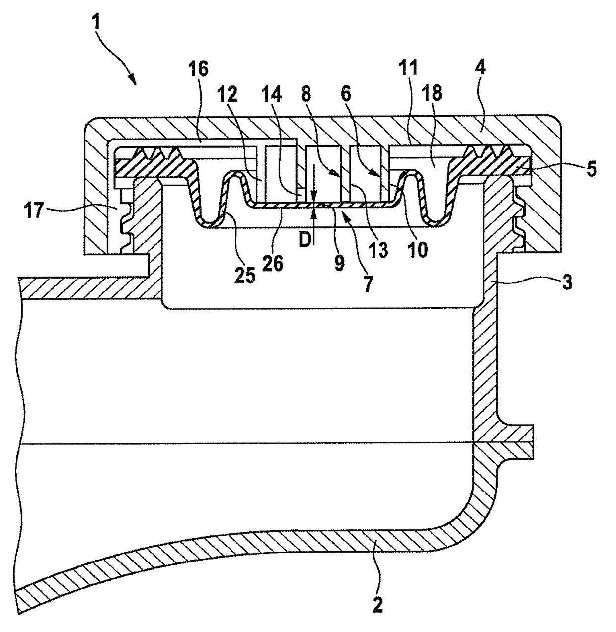
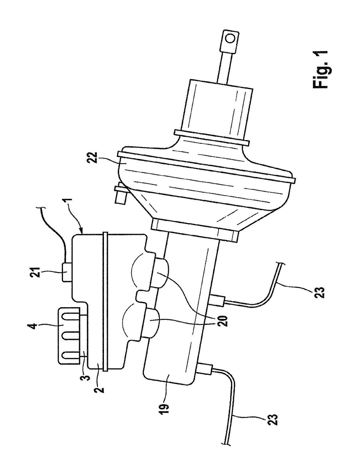
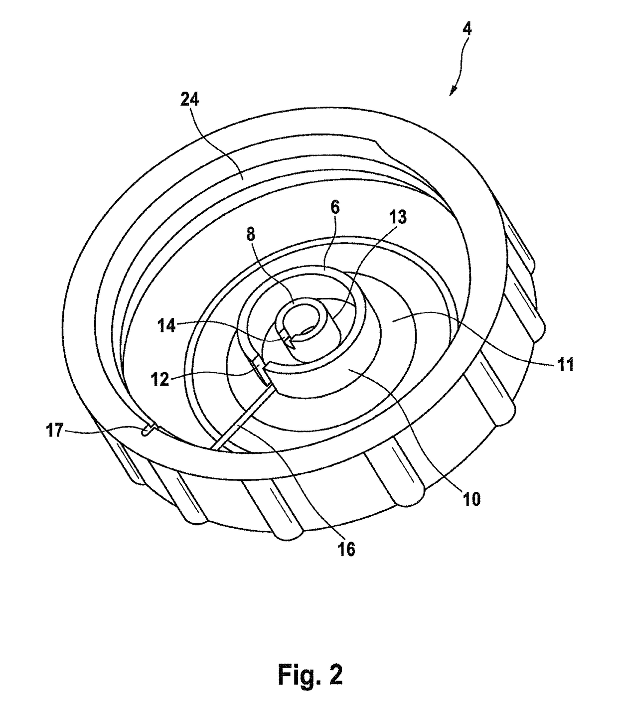
[0024]FIG. 1 shows a pressure medium container 1 according to the invention with a container housing 2 which is mounted, by means of two push-fit connections 20, on a tandem brake master cylinder 19 of a hydraulic motor vehicle brake system, and at the same time is hydraulically connected to the pressure chambers (not shown) in the brake master cylinder 19. However other connections of different design (not shown), for example remote connections by means of flexible or rigid lines, or an indirect connection to a brake master cylinder 19 with the interposition of a further reservoir (not shown), are possible within the invention. The pressure chambers (not shown) of the brake master cylinder 19 are connected hydraulically via brake lines 23 to wheel brakes or brake regulation assemblies. The container housing has a filler pipe 3 which is suitable for filling the pressure medium container and can be closed by a cap 4, preferably by means of a threaded connection. Further connect...


PUM


Abstract

A pressure medium container for a hydraulic motor vehicle brake system. A pressure medium container is provided including a container casing the interior of which can be filled with a pressure medium via a filler pipe and is closed off by a closure cap fixed to the filler pipe. A sealing element made from an elastomeric material is provided between the filler pipe and a bottom of the closure cap. The sealing element has a valve which rests on a support pedestal arranged on the closure cap is closed in a non-actuated initial state and reaches an opened actuated state under the control of differential pressure, whereby a pressure is equalized between an interior of the pressure medium container and an ambient atmosphere. Direction-dependently, the valve has different valve opening resistances.

Description

CROSS REFERENCE TO RELATED APPLICATIONS[0001]This application is the U.S. National Phase Application of PCT International Application No. PCT / EP2013 / 077333, filed Dec. 19, 2013, which claims priority to German Patent Application No. 10 2013 000 041.6, filed Jan. 7, 2013 and 10 2013 005 375.7, filed Mar. 28, 2013, the contents of such applications being incorporated by reference herein.FIELD OF THE INVENTION[0002]The invention concerns a pressure medium container for a hydraulic motor vehicle brake system.BACKGROUND OF THE INVENTION[0003]Pressure medium containers for hydraulic motor vehicle brake systems are known. Usually such pressure medium containers are mounted in the engine bay directly on the brake master cylinder or at least connected thereto hydraulically via lines. In many vehicle variants, the installation conditions present in the engine bay mean that pressure medium containers are used which are formed more linear than cuboid, because for example front windscreens with ...

Claims


Application Information

Patent Timeline
Patent Type & Authority Patents(United States)
IPC IPC(8): B65D51/16F16K15/02B60T11/22B60T11/26B60T13/14B60T17/22B60T17/06
CPCF16K15/02B60T11/22B60T11/26B60T17/06B60T17/222B60T13/142Y10T137/86485
Inventor OTTMANN, SWENNEUMANN, HANS-JURGENKREBS, WERNERSCHLICHT, STEPHANSCHIEL, CHRISTOPH
Owner CONTINENTAL TEVES AG & CO OHG
Why Eureka
Try Eureka