Screw fitting for the passage of fluids, equipment and method for its production

a technology for fluid passage and screw fittings, applied in the direction of adjustable joints, threaded fasteners, fastening means, etc., can solve the problems of reducing the mechanical characteristics of a full screw having the same dimensions, reducing the torque and therefore operating value, and reducing the risk of screw damage during assembly or the necessity of suitably overdimensioning. , to achieve the effect of reducing the pressure drop, reducing the consumption of raw materials, and adequate cleaning

Inactive Publication Date: 2017-08-24
A AGRATI
View PDF0 Cites 0 Cited by
  • Summary
  • Abstract
  • Description
  • Claims
  • Application Information

AI Technical Summary

Benefits of technology

[0022]In particular, an objective of the present invention is to provide a screw fitting for the passage of fluids comprising a stem and an enlarged head positioned at an end of the stem, wherein the stem is at least partially provided with a threaded portion, which is relatively simple and economic to produce.
[0036]Another advantage is having a wide variability of the fluid flow-rate, that can be obtained without reducing the overall robustness of the fitting.

Problems solved by technology

Although these types of screw fitting are generally functional and widely used, they are not without drawbacks.
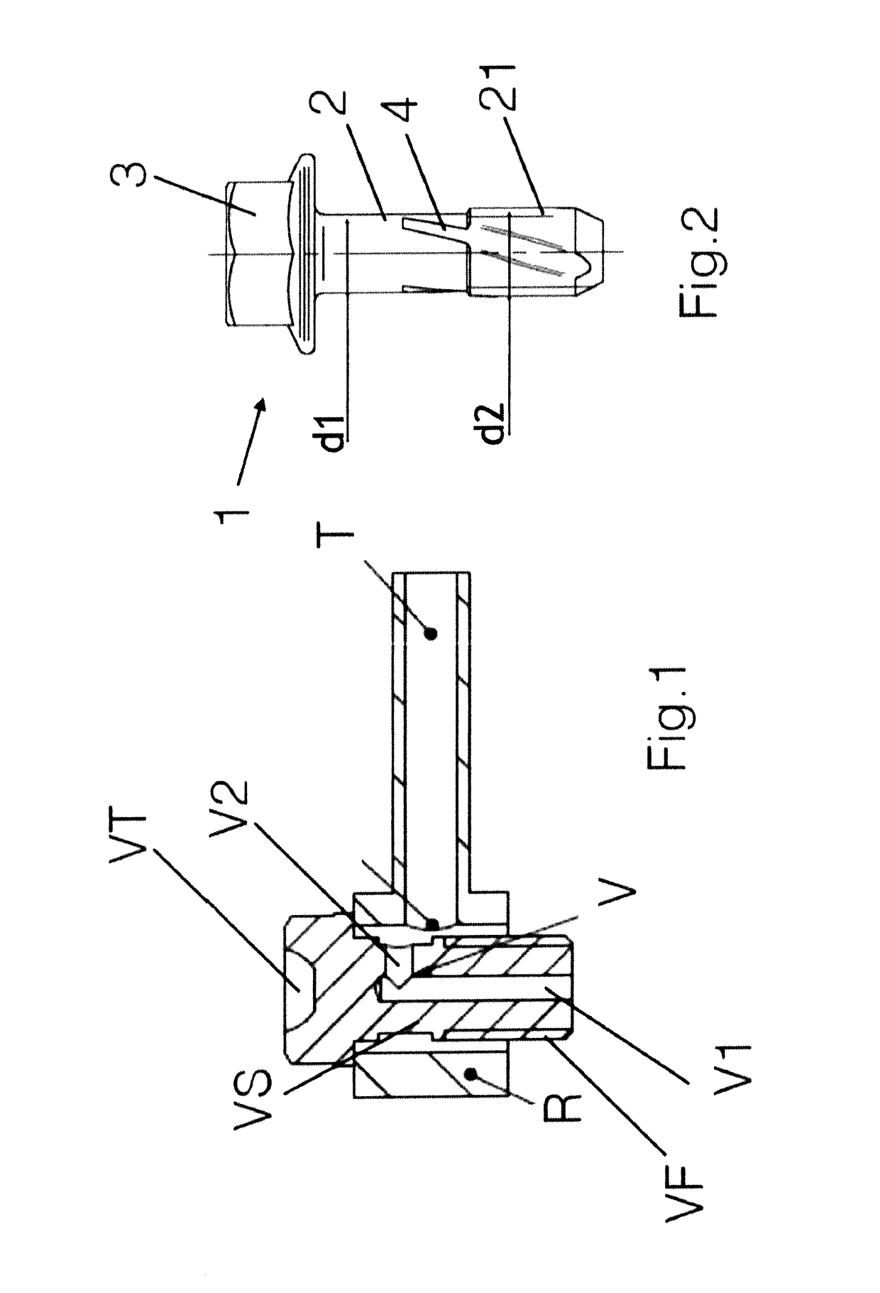
A first drawback is closely related to the production method, by means of chip removal (once the screw V has been produced, the ducts V1 and V2 are formed by axially and radially perforating the screw V itself).
In short, this results in lower mechanical characteristics with respect to a full screw having the same dimensions, associated with the presence of cut fibres, with a consequent lower value of the,breaking torque and therefore operating value.
This leads to the risk of damaging the screw during assembly or the necessity of suitably over-dimensioning it.
Another drawback is linked to the risk of contamination of the ducts V1, V2 (especially in the intersection area of the axial hole V1 and radial hole V2) due to the potential presence of non-evacuated chips, as the washing is difficult mainly due to geometry (small diameters and ducts V1 and V2 intersecting at a right angle).
A further drawback lies in the high pressure drops that are generated in the intersection area of the axial hole V1 and the radial hole V2.
Yet another problem consists in the difficulty of creating imprints for tools different from standard tools (e.g. hexagonal heads).
Another drawback lies in the fact that there is a high consumption of raw material (with a consequent increase in costs), as manufacturing with chip removal inevitably leads to the production of chips and therefore waste material.
A further problem of these known solutions lies in the fact that the overall fluid flow-rate is associated with the screw dimensions and cannot be increased unless the dimensions of the stem are correspondingly increased (with the same robustness), viceversa the axial passage duct would inevitably be too wide and there would be an excessive reduction in the mantle wall of the stem.
Chip removal processing has various drawbacks as it can leave processing residues which, if the component were used in a braking system of a vehicle, could cause dangerous malfunctioning of the system.
The straight cavity, however, hinders the screwing and can only be produced moreover, also in this case, by milling, with the same drawbacks discussed above; furthermore, the straight cavity requires that the thread be produced by chip removal.
As already mentioned, however, this manufacturing method does not provide completely satisfactory results, first of all due to the refinishing of the threaded connection itself and secondly because effecting two milling operations (for the separate production of the thread and cavity) may require a change of tool and two distinct consecutive operations.

Method used


Image

  • Screw fitting for the passage of fluids, equipment and method for its production
  • Screw fitting for the passage of fluids, equipment and method for its production
  • Screw fitting for the passage of fluids, equipment and method for its production

Examples


Embodiment Construction

[0075]Whereas the invention can undergo various modifications and alternative constructions, some preferred embodiments are illustrated in the drawings and are described in detail hereunder.

[0076]It should be understood, however, that there is no intention of limiting the invention to the specific embodiment illustrated but, on the contrary, it intends to cover all the modifications, alternative constructions and equivalents that fall within the scope of the invention as defined in the claims.

[0077]The use of “for example”, “etc”, “or” indicates non-exclusive alternatives without any limitation unless otherwise specified.

[0078]The use of “comprises” means “comprises, but not limited to” unless otherwise specified.

[0079]Indications such as “vertical” and “horizontal”, “upper” and “lower” (without other indications) should be read with reference to the assembly (or operative) conditions and referring to normal terminology used in everyday language, wherein “vertical” indicates a direc...


PUM


Abstract

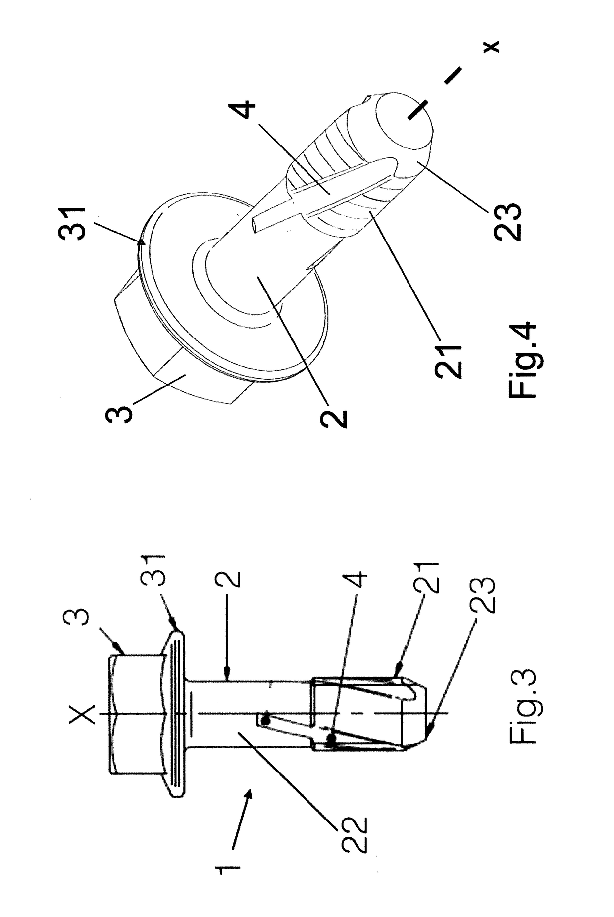
A screw fitting for the passage of fluids includes a stem and an enlarged head positioned at an end of the stem the stem being at least partially provided with a threaded portion that includes at least a throat for the passage of a fluid, formed on an outer portion of the stem and extending at least through the threaded portion.

Description

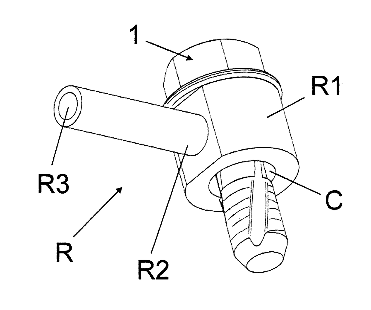
TECHNICAL FIELD[0001]The present invention relates to the field of screw fittings for the passage of fluids, between different elements, typically an intake system (tube) and an implementation system (cylinder).STATE OF THE ART[0002]In the state of the art, every time a hydraulic tube must be connected to an actuator, passages must be envisaged for a fluid in the connection element: it contemporaneously exerts, in fact, the function of a passage for the fluid and that of a mechanical coupling between the tube and actuator.[0003]As a first example, and with reference to FIG. 1, the case can be considered of the braking circuit of a vehicle: the coupling of the tube T, which carries the oil to the brake pliers (actuator), is effected by means of an eyelet fitting R in which a screw V provided with a duct V1, V2 for the passage of the oil, is housed; the eyelet fitting R is connected and in fluid communication with the tube T, whereas the threaded portion VF of the screw V is engaged o...

Claims


Application Information

Patent Timeline
Patent Type & Authority Applications(United States)
IPC IPC(8): F16B37/08F16B33/02F16L27/093
CPCF16B37/085F16B33/02F16L27/093
Inventor CAZZAMANI, ENRICO
Owner A AGRATI
Why Eureka
Try Eureka