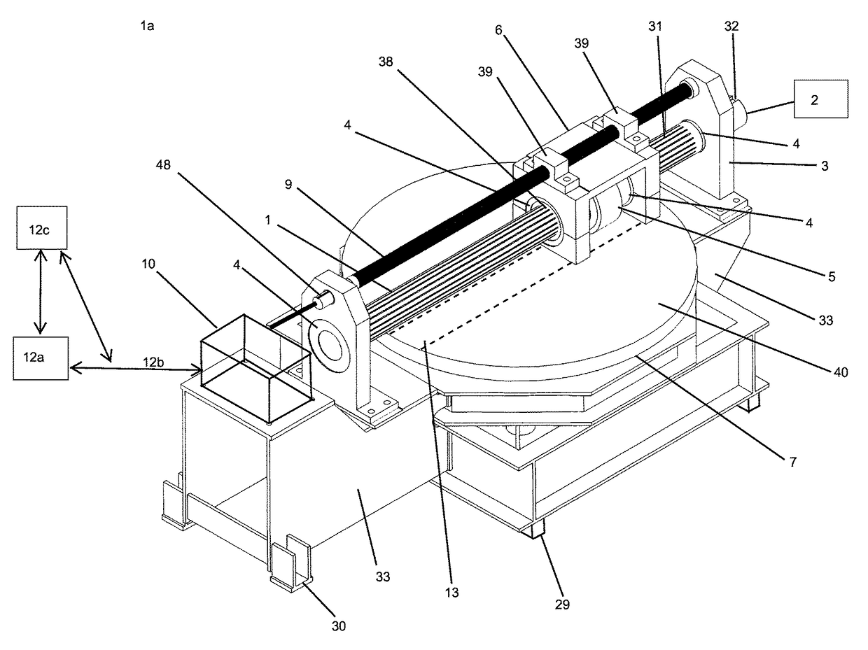
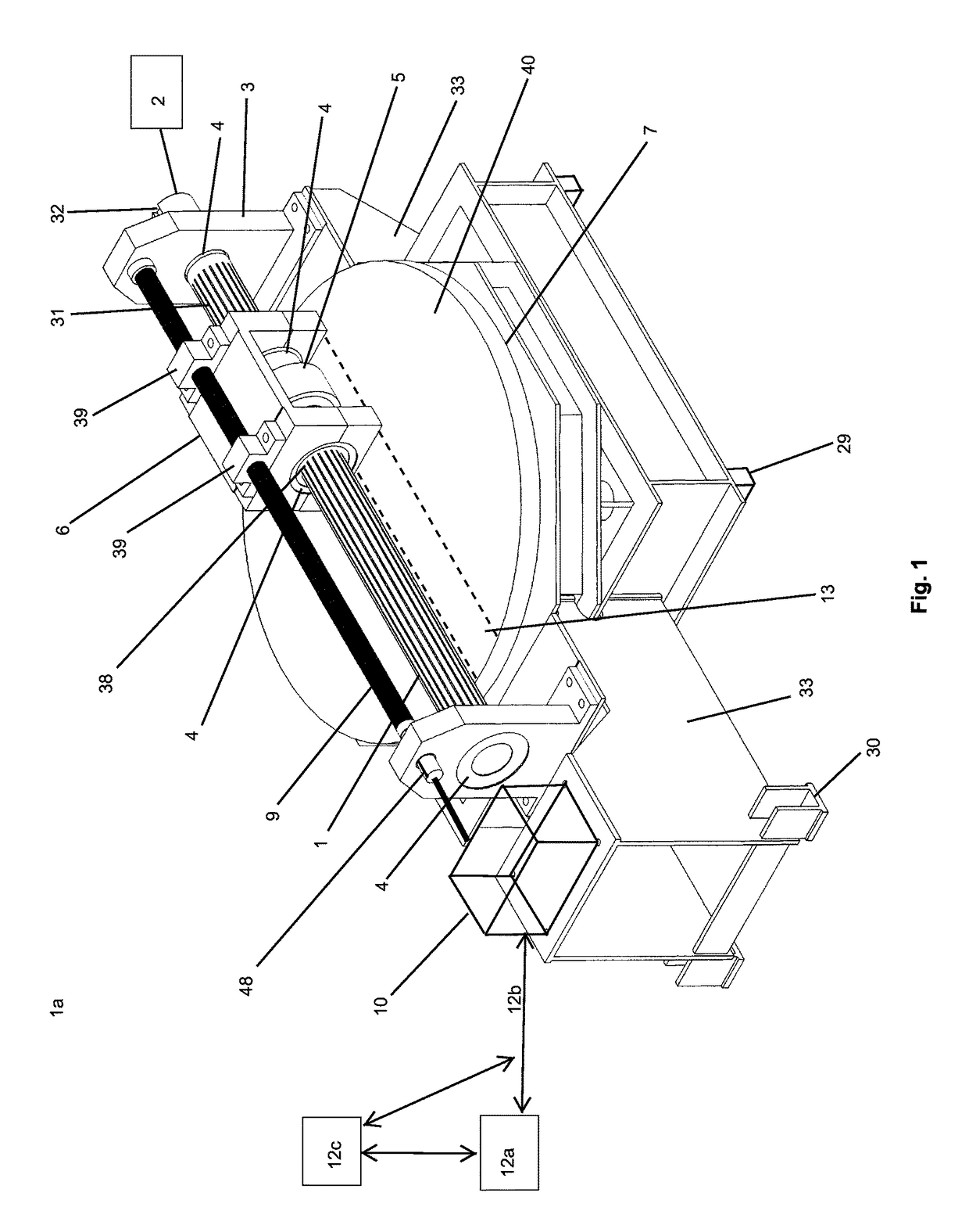
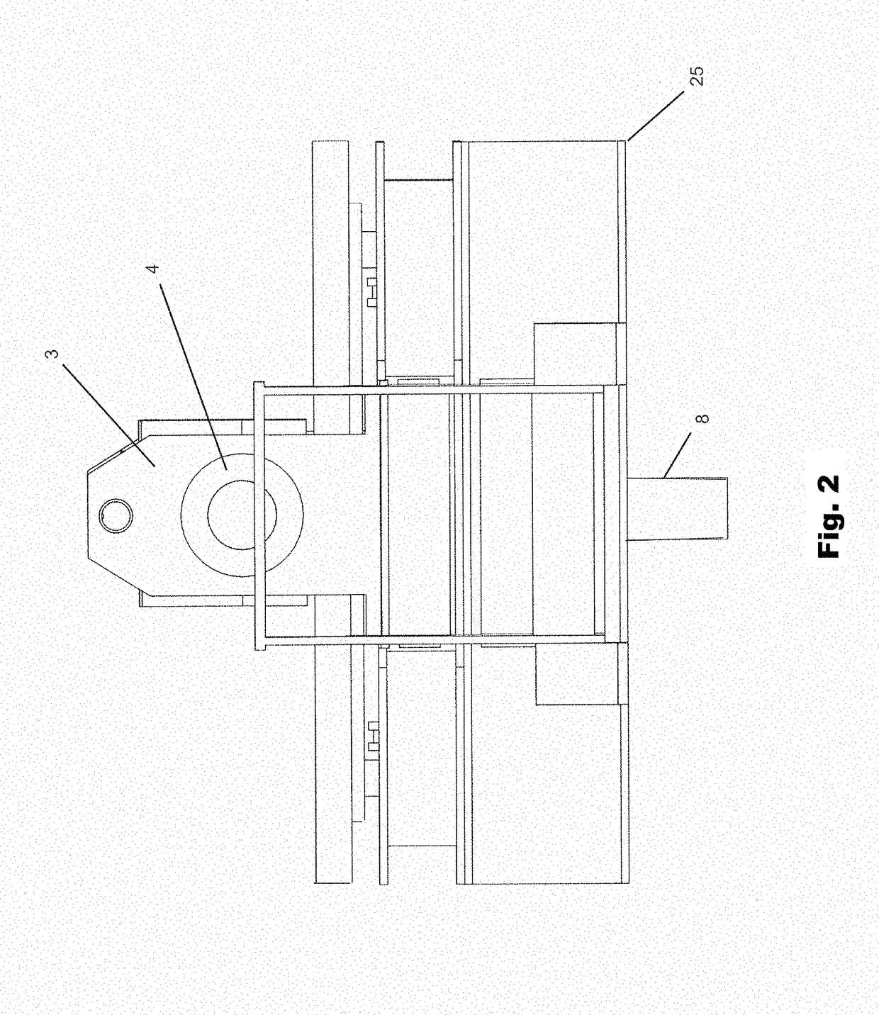
[0007]As seen in the various figures, in a basic embodiment the inventive technology includes a variable coupler drive (1a) utilizing perhaps a rotating or rotatable cylinder (1), driven for example by a motor, which may generate a rotational drive input (2) at a desired speed. This rotating cylinder (1) may be dynamically coupled, for example in a slidable manner, with a spinner (5) element secured perhaps within an adaptable support bracket (6). Such adaptable support bracket (6) may be a non-rotational support joined with a spinner (5) through a rotational joint (4), such as a bearing joint allowing a spinner (5) to freely rotate within a bracket. This rotating spinner may be in contact, or brought into contact with a drive table (7) causing a controlled rotation. As detailed in the various figures disclosed herein, this drive table (7) may be supported by one or more rotational support system(s), such as a rotational support base (20) and may be further coupled to a rotatable drive shaft (8) which may be utilized to transmit the systems power output. Again, as shown in the figures, this adaptable support bracket (6) may be joined with a variable position driver (10), through for example a variable position track (9) which may allow it—and the coupled spinner (5)—to move across the circumference of the drive table. In this manner, the position of the rotating spinner (5) may establish the system's drive ratio output based on the position of the spinner (5) in relation to the drive table's central axis. Such drive-ratio may be continuously and dynamically altered based on the position of the spinner in relation to the drive table's central axis. As such, the inventive technology may achieve a desired drive-ratio without, perhaps, the need to neither alter the system's power input nor use traditional gearing “teeth” and / or a gear train, or other traditional step-wise gear mechanisms.
[0008]Moreover, the inventive technology in some embodiments may allow for dynamic control of the drive system's output by adjusting the spinner's (5) position along the drive table (7). Naturally, this dynamic control capability may allow the system's power output to not only remain constant, even during fluctuations of any power inputs, but also may allow for rapid increases and / or decreases in power output, perhaps in response to an external demand or load resistance by dynamically adjusting the spinner (5) to a new drive ratio position along the drive table (7). Another additional embodiment of such a variable coupler drive (1a) may allow for a rapid change in the direction of the drive's output without any traditional gearing or other switching mechanisms requiring the input to be turned off. In one embodiment, for example to reverse the rotational power output of the drive system, the variable coupler drive may adjust the spinner element from one side of the drive table to the opposite side or alternate variable drive ratio directional region (43), reversing the table's direction, and thus reversing the drive output as well without interruption of the systems drive input.
[0009]Additional embodiments include method and apparatus to engage as well as disengage the drive table (7) from the spinner (5). In one such embodiment a drive table lift may allow a centrally positioned drive table (7) to be raised and lowered to contact a rotating spinner (5). In this manner a drive input, in this case a rotational drive input (2) provided by a motor may be dynamically coupled and / or de-coupled from the drive table further transmitting and / or stopping transmission of such input. Such a variable drive coupler switch may allow greater control of the system's output as well as a coupling and / or de-coupling switch modifying the systems power output.
[0010]Moreover, various positions along the drive table (7) may include spaced positions where the rotating spinner (5) may not be in contact with the drive table's surface generating, for example, a neutral “de-coupled” position. Finally, in some embodiments, this variable drive coupler may be easily accessible for repairs or replacement. For example, as discussed below, a centrally positioned translatable drive table support mount (25) may be detachable from the other supports through translatable interfaces (50) or connections and may slide, for example, on a slide bearing (29). This modular design may be adapted and allow for the quick removal and replacement of any of the various elements listed.
[0015]Another objective of the current inventive technology may be to provide methods and apparatus for a variable drive coupler that may be quickly coupled and / or de-coupled through a coupler lift system. Another objective of the current inventive technology may be to provide methods and apparatus for a variable drive coupler that may be modular and / or easily accessible for replacement of parts, maintenance and / or repairs. Another objective of the current inventive technology may be to provide methods and apparatus for a rotational propeller drive system that may allow rotational movement of a propeller drive as well as independent rotational movement of a rotational propeller drive housing.