Safety cone with controlled illumination

a safety cone and controlled technology, applied in the field of safety or sports cones, can solve the problems of difficult to see conventional cones, and achieve the effects of preventing unwanted activation of illumination devices, facilitating use, and increasing illumination intensity

Active Publication Date: 2017-09-26
P&P IMPORTS
View PDF6 Cites 0 Cited by
  • Summary
  • Abstract
  • Description
  • Claims
  • Application Information

AI Technical Summary

Benefits of technology

[0003]A safety or sports cone with controlled illumination is provided that is durable and easy to use. The cone has a light-transmitting body with an illumination device housing integrated into the top of the body. The illumination device housing contains a support ring upon which the illumination device rests, and a housing cap that provides access to the illumination device. The illumination device includes a light-emitting diode (LED) module, an LED actuator, a battery, and a battery housing. The illumination device fits within, and it protected by, a transparent shell. A reflective platform increases the illumination intensity at the top of the cone and provides additional protection from physical damage and contaminants. The illumination is activated and deactivated by pressing the center of the housing cap that causes contact with the LED actuator. One or more ridges extending from the inner surface of the body below the support ring prevent unwanted activation of the illumination device when cones are stacked on top of each other.

Problems solved by technology

However, in low-light conditions where the observer does not have the benefit of a directional light source (e.g. vehicle's headlights) to illuminate the cone, such as in nighttime sports activities, conventional cones may be difficult to see.

Method used


Image

  • Safety cone with controlled illumination
  • Safety cone with controlled illumination
  • Safety cone with controlled illumination

Examples


Embodiment Construction

[0015]In the following discussion, numerous specific details are set forth to provide a thorough understanding of the present invention. However, those skilled in the art will appreciate that the present invention may be practiced without such specific details. In other instances, well-known elements, processes or techniques have been briefly mentioned and not elaborated on in order not to obscure the present invention in unnecessary detail and description. Moreover, specific details and the like may have been omitted inasmuch as such details are not deemed necessary to obtain a complete understanding of the invention, and are considered to be within the understanding of persons having ordinary skill in the relevant art.

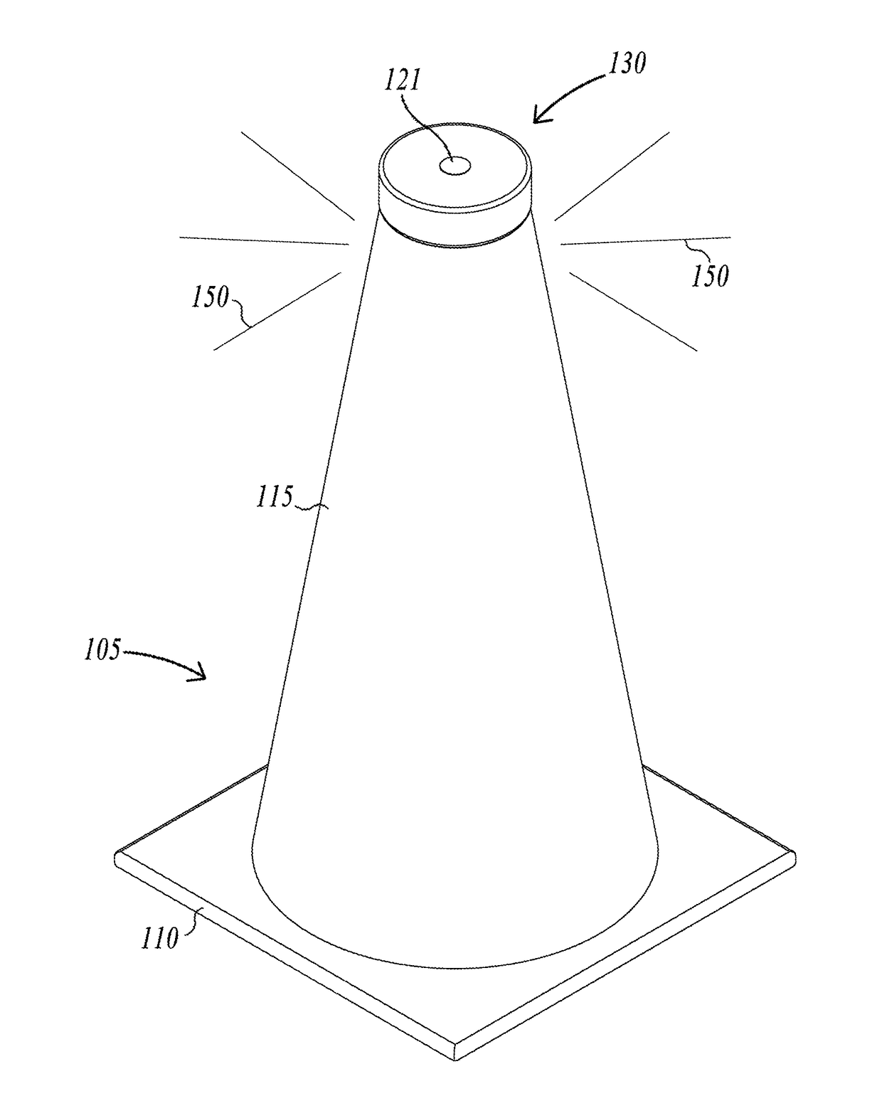
[0016]FIG. 1 illustrates an isometric view of the illuminated cone with installed housing cap as fully assembled and ready for use. The device of the present invention comprises a modified self-standing cone 105 with base portion 110 and cone portion 115. The termina...


PUM


Abstract

A safety or sports cone with controlled illumination is provided that is durable and easy to use. The cone has a light-transmitting body with an illumination device housing integrated into the top of the body that houses an illumination device that rests on a support ring and is accessed by a housing cap. The illumination device includes a light-emitting diode (LED) module, an LED actuator, a battery, and a battery housing. The illumination device is covered by a protective transparent shell. A reflective platform increases the illumination intensity at the top of the cone and provides additional protection from physical damage and contaminants. The illumination is activated and deactivated by pressing the center of the housing cap to affect the LED actuator. One or more ridges extending from the inner surface of the body below the support ring prevent unwanted activation of the illumination device during cone stacking.

Description

FIELD OF THE INVENTION[0001]The present invention relates to safety or sports cones.BACKGROUND OF THE INVENTION[0002]Plastic or rubber cones of various sizes are commonly used to set boundaries and designate dangerous or sensitive areas. For example, traffic or safety cones are used in traffic, construction, and accident settings to halt or direct traffic and passers-by. In sports, a smaller and lighter version of these cones is used to designate various boundaries such as the corners, and other portions of a playing field, including goal areas. Safety and sports cones are used during the day as well as nighttime, and visibility is a critical aspect of the cone. As a result, safety and sport cones are often given a highly noticeable, distinctive color such as bright orange or green. Moreover, some cones include a reflective material to be more visible when light is shined on them. However, in low-light conditions where the observer does not have the benefit of a directional light so...

Claims


Application Information

Patent Timeline
Patent Type & Authority Patents(United States)
IPC IPC(8): F21L4/00H05B33/08H05B44/00
CPCE01F9/615E01F9/623H05B33/0857E01F9/654H05B45/00Y02B20/30H05B45/20
Inventor TANOURY, PETERENGLER, PETER
Owner P&P IMPORTS
Why Eureka
Try Eureka