
Liquid crystal display device and method for manufacturing same

a liquid crystal display and liquid crystal technology, applied in the direction of instruments, coatings, transportation and packaging, etc., can solve the problems of deteriorating display performance, insufficient increase of aperture ratio, display defects, etc., and achieve good alignment stability and improved image sticking characteristics

Active Publication Date: 2017-09-26
JNC CORP +1
View PDF11 Cites 10 Cited by
  • Summary
  • Abstract
  • Description
  • Claims
  • Application Information

AI Technical Summary

Benefits of technology

The present invention is about improving the image stickiness and alignment stability of a liquid crystal display by using an alignment film with a specific structure and a liquid crystal molecule with negative dielectric anisotropy. The technical effect is better quality and stability of the liquid crystal display.

Problems solved by technology

When a liquid crystal composition having positive (+) dielectric anisotropy is used for these devices, liquid crystal molecules are aligned in an electric field line direction in a state that a voltage is applied thereto and thus in a vertical direction around an electrode, and this may cause display defects.
Since these display defects need to be masked in order to use these devices as a liquid crystal display (LCD), there is a problem of not sufficiently increasing an aperture ratio.
However, this method of using a photodegradation reaction of an alignment film (hereinafter referred to as a photodegradation method) has a problem of deteriorating display performance such as leaving degradation products (monomolecule components) of the alignment film and deteriorating image sticking characteristics, thermal stability, electrical stability, and the like (Patent Document No. 7).

Method used


Image

  • Liquid crystal display device and method for manufacturing same
  • Liquid crystal display device and method for manufacturing same
  • Liquid crystal display device and method for manufacturing same

Examples


synthesis example 1

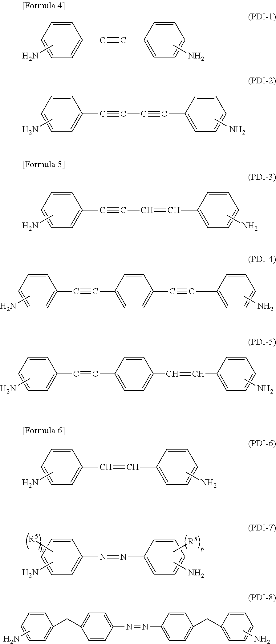
[0436]0.2102 g of diamine (DI-5-1, m=2), 0.0664 g of diamine (DI-9-1), 0.2082 g of diamine (PDI-6-1), 0.5778 g of diamine (PDI-7-1), and 18.5 g 50 mL of dehydration NMP were put in a brown four-necked flask equipped with a thermometer, a stirrer, an inlet for feeding a raw material, and another inlet for introducing nitrogen gas and then stirred and dissolved under a dry nitrogen stream. Subsequently, 0.1268 g of acid dianhydride (AN-1-13), 1.8106 g of acid dianhydride (AN-4-17, m=8), and 18.5 g of dehydrated NMP were added thereto and continuously stirred at room temperature for 24 hours. Then, 10.0 g of BC was added to the reaction solution, obtaining a polyamic acid solution having a polymer solid concentration of 6 wt %. This polyamic acid solution is called PA1. A weight average molecular weight of the polyamic acid included in the PA1 was 39,400.

synthesis examples 2 to 8

[0437]As shown in Table 1, polyamic acid solutions PA2 to PA8 respectively having a polymer solid concentration of 6 wt % were prepared according to the same method as Synthesis Example 1, except for changing the tetracarboxylic dianhydride and the diamine. Table 1 shows the weight average molecular weight results of the obtained polyamic acids as well as the result of Synthesis Example 1.

[0438]

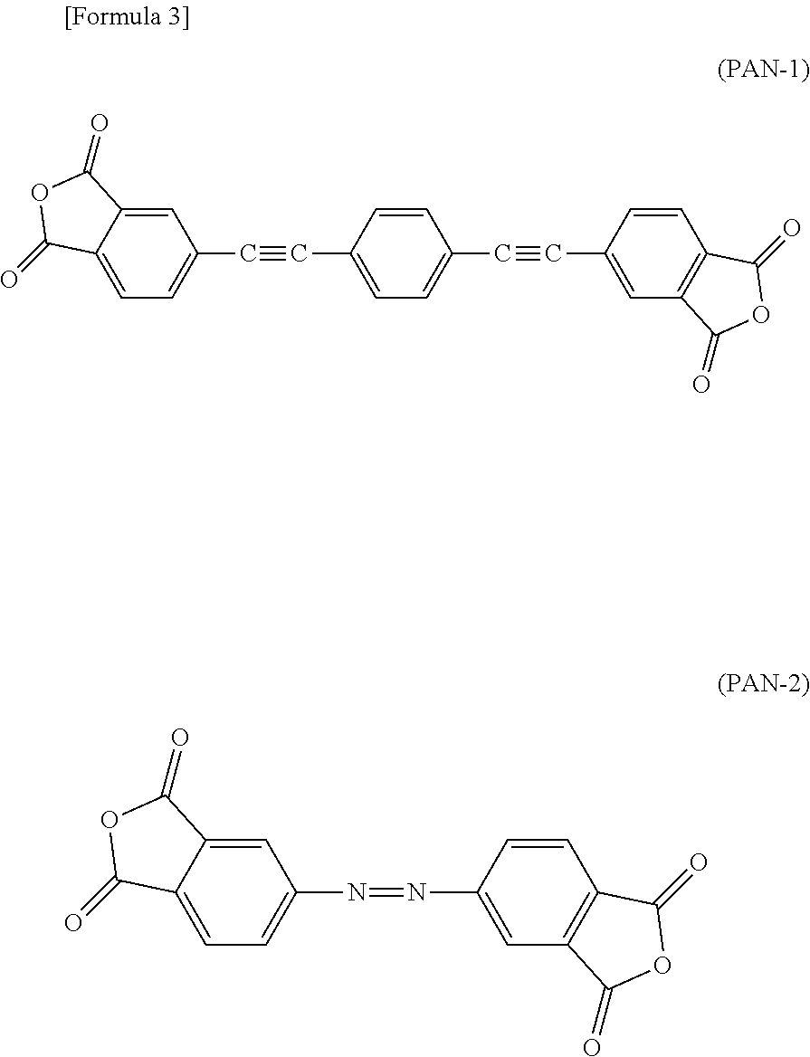
TABLE 1SynthesisPolyamicTetracarboxylicWeight averageEx. No.acid No.dianhydride(mol %))Diamine(mol %)molecular weight1PA1AN-1-13 (10)DI-5-1 (m = 2)(20)39,400AN-4-17 (m = 8) (90)DI-9-1 (5)PDI-6-1(20)PDI-7-1(55)2PA2AN-3-1 (30)DI-5-1 (m = 2)(50)42,000AN-4-17 (m = 8) (70)PDI-7-1(50)3PA3AN-4-17 (m = 8)(100)DI-5-1 (m = 4)(40)32,000PDI-7-1(60)4PA4AN-4-21(100)DI-5-1 (m = 4)(25)21,700PDI-7-1(75)5PA5AN-4-21(100)DI-5-4(50)28,600PDI-7-1(50)6PA6PAN-2(100)DI-2-1(20)40,700PDI-7-1(80)7PA7AN-4-17 (m = 8)(100)DI-19-7(R41═C7H15) (3)17,500PDI-7-1(97)8PA8AN-4-17 (m = 8)(100)DI-4-13(10)15,200DI-16-5(R35═C5H11) (5)...

synthesis example 9

[0440]0.7349 g of diamine (DI-4-1) and 18.5 g of dehydration NMP were put in a brown 50 mL four-necked flask equipped with a thermometer, a stirrer for feeding a raw material, and another inlet for introducing nitrogen gas and then stirred and dissolved under a dry nitrogen stream. Subsequently, 0.6732 g of acid dianhydride (AN-1-1), 1.5918 g of acid dianhydride (AN-4-28), and 18.5 g of dehydrated NMP were added thereto at room temperature and continuously stirred for 24 hours. Then, 10.0 g of BC was added to the reaction solution, obtaining a polyamic acid solution having a polymer solid concentration of 6 wt %. This polyamic acid solution was called PA9. A weight average molecular weight of the polyamic acid included in the PA9 was 51,000.


PUM

PropertyMeasurementUnit
mole ratioaaaaaaaaaa
temperatureaaaaaaaaaa

Abstract

The present invention relates to a liquid crystal display device including a pair of a substrate arranged opposite to each other, an electrode group disposed on one side or both sides of the pair of substrates facing each other, a plurality of active devices connected to the electrode group, a liquid crystal alignment film disposed on each facing side of the pair of substrates, and a liquid crystal layer interposed between the pair of substrates, wherein the liquid crystal alignment film is manufactured by irradiating linearly polarized light to a film obtained from polyamic acid or a derivative thereof having a photoisomerization structure in the main chain or a film being subject to heat-baking so as to provide alignment-controlling capability, and the liquid crystal layer is a liquid crystal composition having negative (−) dielectric anisotropy. By the present invention, a liquid crystal display device having improved image sticking characteristics and good alignment stability is provided.

Description

TECHNICAL FIELD[0001]The present invention relates to a liquid crystal display device including a photo-alignment film, and a method of manufacturing the same.TECHNICAL BACKGROUND[0002]A liquid crystal display has been widely supplied to the public for various uses according to development and progress of technology of widening a viewing angle and technology of a motion picture.[0003]Recently, a method of driving liquid crystals has been improved in order to provide a liquid crystal display (LCD) having higher precision and a wide viewing angle. For example, Patent Document No. 1 discloses an IPS (In-Plane Switching) mode liquid crystal display using an electric field parallel to the surface of a glass substrate. In addition, Patent Document No. 2 discloses a liquid crystal display (LCD) having an improved aperture ratio by using FFS (Fringe-Field Switching) technologies obtained by further improving the IPS technology.[0004]Further, a liquid crystal composition, an alignment film m...

Claims


Application Information

Patent Timeline
Patent Type & Authority Patents(United States)
IPC IPC(8): C09K19/00C09K19/24C09K19/34C09K19/38G02F1/1337C09D179/08C09K19/20C09K19/54C08G73/10G02F1/1343C09K19/12C09K19/18C09K19/30C09K19/32G02F1/137G02F1/1333C09K19/16
CPCC09K19/542C08G73/1042C08G73/1067C08G73/1071C08G73/1078C08G73/1096C09D179/08C09K19/2007C09K19/24C09K19/3003C09K19/3066C09K19/3402C09K19/3809G02F1/133723G02F1/133788G02F1/134363C08K5/357C08L63/00C08K5/353C09K2019/122C09K2019/123C09K2019/161C09K2019/181C09K2019/188C09K2019/301C09K2019/3009C09K2019/3016C09K2019/3036C09K2019/3037C09K2019/325C09K2019/3408C09K2019/3422C09K2019/548G02F2001/13712G02F2001/133397Y10T428/1005G02F1/133397G02F1/13712C09K2323/02C09K2323/00
Inventor KATANO, YUKOHIRANO, YUKIOIZAWA, KEISUKEKONDO, FUMITAKA
Owner JNC CORP
Learn More