
Energy weight storage

a technology of energy weight and energy storage, applied in the field of energy weight storage systems, can solve the problems of inability to meet the needs of energy storage, none of the technologies fared well from the perspectives of experts, etc., and achieve the effects of reducing production costs, increasing energy storage capacity, and reducing production costs

Active Publication Date: 2017-08-29
BOONE DANIEL N
View PDF9 Cites 0 Cited by
  • Summary
  • Abstract
  • Description
  • Claims
  • Application Information

AI Technical Summary

Benefits of technology

Weight storage systems offer potential for better cost-effectiveness, scalability, and reduced environmental impact, achieving reliability and consistency in energy supply by leveraging existing technologies and eliminating water usage limitations, enabling a fully renewable energy infrastructure.

Problems solved by technology

The most prominent obstacle to the successful development of renewable energy seems to be the lack of suitable and effective means of energy storage.
In brief, none of the technologies fared well from the perspectives of these experts.

Method used


Image

  • Energy weight storage
  • Energy weight storage
  • Energy weight storage

Examples


Embodiment Construction

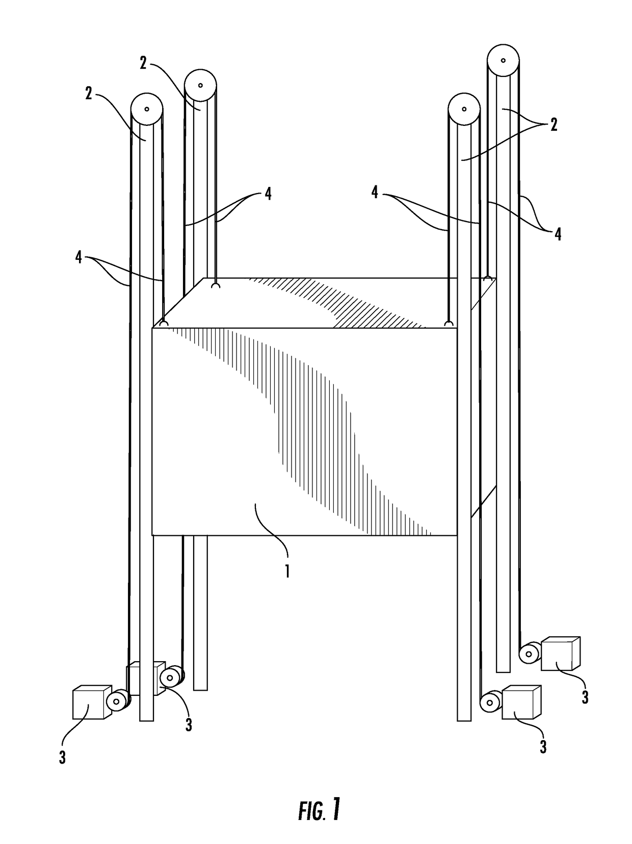
[0025]FIG. 1 is a perspective schematic showing a rectangular tank 1 supported at its corners by four shafts 2. Motors 3 located at the ground level are each a synchronized winch system able to hoist the rectangular tank 1, which, when fully raised, may be lowered when needed to make the motors act as generators to produce electricity. The winch system uses cables 4 to raise and lower the rectangular tank.

[0026]FIG. 2 is a front view ground level schematic showing part of a weight storage framework. In the center is one unit 5 and another partially shown unit 6 is adjacent on each side. Very heavy, flat horizontal sections 7 are supported by the framework shafts 8 at each edge and corner. In each of the three units, one flat section is shown being raised up to store energy 9. When all sections are raised at the top, they may be lowered when needed to generate electricity. What is indicated in FIG. 2 at the bottom are means to raise or lower the flat sections 10. These devices may be...


PUM


Abstract

A first weight system for storing energy comprises a support platform with a lifting station having a plurality of vertically extending shafts, a cable and a motor located at ground level. This weight system hoists a heavily weighted device upwardly along the vertically extending shafts; holds it in a raised position and then lowers it along these same shafts to turn the motors and generate energy. The weighted device can include one or more flat rectangular containers or a weighted box. A second system employs a pair of containers connected to one another on an inclined track by a cable that can be moved about a guide wheel at a top of the track. The track further includes a media collection area, container filling area and means for conveying media from the bottom to the top of the inclined track. A third system pulls a plurality of large heavy wheels up an inclined track with wind power for subsequent lowering to turn a motor and generate energy.

Description

CROSS-REFERENCE TO RELATED APPLICATIONS[0001]This is a perfection of Provisional Application Ser. No. 62 / 062,876, filed on Oct. 11, 2014, the disclosure of which is fully incorporated by reference herein.FIELD OF THE INVENTION[0002]The present invention discloses a variety of energy storage systems designed to store energy from any source, such as fossil fuel generation plants, hydroelectric installations, nuclear stations, wind farms, solar fields, and others. The energy is stored by means of raising heavy entities against gravity and holding them in storage when fully raised. When there is a demand for electricity, the heavy entities will be lowered and the resulting release of energy can run generators to supply the electrical grid. Since these energy storage systems all operate by “working against gravity” they will be referred to in general as “weight storage” systems, to distinguish them from other energy storage technologies, such as pumped hydro, compressed air, molten salts...

Claims


Application Information

Patent Timeline
Patent Type & Authority Patents(United States)
IPC IPC(8): F03G3/00F03G3/04
CPCF03G3/00F03G3/04
Inventor BOONE, DANIEL N.
Owner BOONE DANIEL N
Learn More