
Single-pole, single current path switching system and method

a switching system and single current technology, applied in the field of single-pole, single-current path switching system and method, can solve the problems of non-instantaneous opening and closing of switching devices, noise oscillation, and small delay between

Active Publication Date: 2017-08-08
ROCKWELL AUTOMATION TECH
View PDF116 Cites 32 Cited by
  • Summary
  • Abstract
  • Description
  • Claims
  • Application Information

AI Technical Summary

Benefits of technology

The present disclosure relates to improving the operation and configuration of switching devices, particularly in industrial, commercial, material handling, process, and manufacturing settings. The technical effects of the patent include reducing likelihood and magnitude of electric arcing and current oscillations when making or breaking a switching device, as well as increasing the operational flexibility of a wye-delta starter by opening and closing switching devices at specific points on the electric power waveform. Additionally, the patent discusses the issue of restarting the electric motor as soon as possible while still spinning, but the changing frequency of the motor can create a "beat" condition, which may result in current oscillations and torque oscillations.

Problems solved by technology

As the switching devices open or close, electric power may be discharged as an electric arc and / or cause current oscillations to be supplied to the load, which may result in torque oscillations.
However, the opening and closing of the switching devices are generally non-instantaneous.
For example, there may be a slight delay between when the make instruction is given and when the switching device actually makes (i.e., closes).
Similarly, there may be a slight delay between when break instruction is given and when the switching device actually breaks (i.e., opens).
More specifically, the electric motor may be started by connecting the windings in the motor in a wye configuration to reduce voltage supplied to the windings, which may also reduce the torque produced by the motor.
However, as described above, opening and closing the switching devices to connect the electric motor in the wye configuration and to transition from the wye configuration to the delta configuration may discharge electric power (e.g., arcing) and / or cause current oscillations to be supplied to the motor.
After the electric motor is spinning, electric power may be disconnected from the motor for various reasons, such as a brownout or a lightning strike.
Once power is disconnected, the momentum of the rotation may keep the motor spinning, but friction (e.g., air resistance) may begin to slow the motor.
Therefore, the motor may be out of phase from the source when re-closing the switching devices to reconnect electric power to the motor, which may result in current oscillations and / or torque oscillations.

Method used


Image

  • Single-pole, single current path switching system and method
  • Single-pole, single current path switching system and method
  • Single-pole, single current path switching system and method

Examples


Embodiment Construction

[0100]One or more specific embodiments of the present disclosure will be described below. In an effort to provide a concise description of these embodiments, all features of an actual implementation may not be described in the specification. It should be appreciated that in the development of any such actual implementation, as in any engineering or design project, numerous implementation-specific decisions must be made to achieve the developers' specific goals, such as compliance with system-related and business-related constraints, which may vary from one implementation to another. Moreover, it should be appreciated that such a development effort might be complex and time consuming, but would nevertheless be a routine undertaking of design, fabrication, and manufacture for those of ordinary skill having the benefit of this disclosure.

[0101]When introducing elements of various embodiments of the present disclosure, the articles “a,”“an,”“the,” and “said” are intended to mean that th...


PUM

PropertyMeasurementUnit
coil current waveformsaaaaaaaaaa
frequencyaaaaaaaaaa
frequencyaaaaaaaaaa

Abstract

One embodiment describes a three-phase electromechanical switching device, which includes three single-phase switching devices mechanically and electrically coupled in parallel with one another, each single-phase switching device including a direct current electromagnetic operator that in operation receives a direct current control signal for switching of the device, stationary contacts disposed in a respective device housing, and a movable assembly that in operation is displaced by energizing the operator and that include movable contacts that open and close, with the stationary contacts, a single current carrying path through the respective single-phase switching device; in which each of the single-phase switching devices receives control signals from control circuitry coupled to the operators of the respective single-phase switching devices to cause at least one of the single-phase switching devices to open or close the single current carrying path at a desired time coordinated with a current zero-crossing or a predicted current zero-crossing of a phase of three-phase power.

Description

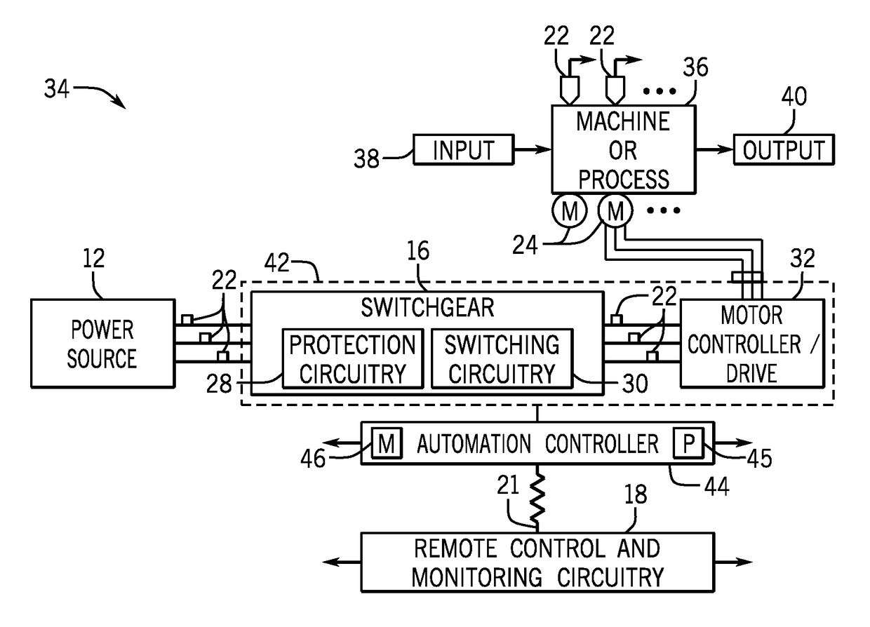
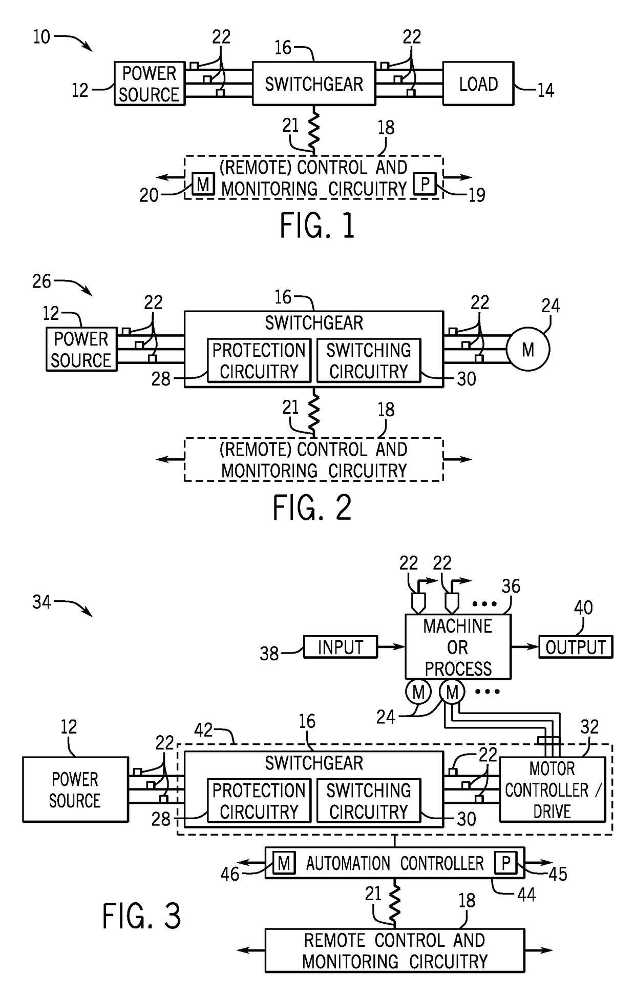
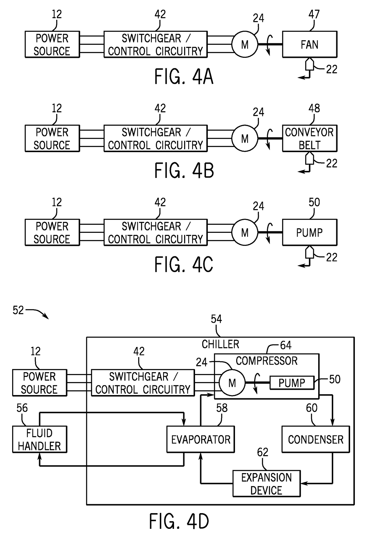
BACKGROUND[0001]The present disclosure relates generally to switching devices, and more particularly to operation and configuration of the switching devices.[0002]Switching devices are generally used throughout industrial, commercial, material handling, process and manufacturing settings, to mention only a few. As used herein, “switching device” is generally intended to describe any electromechanical switching device, such as mechanical switching devices (e.g., a contactor, a relay, air break devices, and controlled atmosphere devices) or solid state devices (e.g., a silicon-controlled rectifier (SCR)). More specifically, switching devices generally open to disconnect electric power from a load and close to connect electric power to the load. For example, switching devices may connect and disconnect three-phase electric power to an electric motor. As the switching devices open or close, electric power may be discharged as an electric arc and / or cause current oscillations to be suppl...

Claims


Application Information

Patent Timeline
Patent Type & Authority Patents(United States)
IPC IPC(8): F02D41/20H01H47/22H01H50/00H01H47/00G01K7/00H01H50/16G01R31/327H01H47/26H01H9/26H02P1/26H01H89/00H01H47/02H01H50/38H01H50/32H01H9/56H02P1/32H01H9/30H01H71/08
CPCG01R31/327G01K7/00H01H9/26H01H47/002H01H47/02H01H47/22H01H47/26H01H50/002H01H50/16H01H50/323H01H50/38H01H89/00H02P1/26H01H9/56H01H71/082H01H2009/307H02P1/32G01R31/3274G01R31/44
Inventor BOCK, CHRISTOPHER H.WIELOCH, CHRISTOPHER J.KINSELLA, JAMES J.DZIEKONSKI, STEFAN T.
Owner ROCKWELL AUTOMATION TECH
Learn More