
Exhaust-gas turbocharger

a turbocharger and exhaust gas technology, applied in the direction of combustion engines, gas turbine plants, machines/engines, etc., can solve the problems of increasing the wear of adjoining components

Inactive Publication Date: 2017-08-08
BORGWARNER INC
View PDF17 Cites 4 Cited by
  • Summary
  • Abstract
  • Description
  • Claims
  • Application Information

AI Technical Summary

Benefits of technology

The invention aims to create an exhaust-gas turbocharger that is inexpensive to make and operate with low maintenance. Additionally, it should be dependable and reliable.

Problems solved by technology

Corresponding vibrations arise in the control rod, leading to increased wear of the adjoining components.

Method used


Image

  • Exhaust-gas turbocharger
  • Exhaust-gas turbocharger
  • Exhaust-gas turbocharger

Examples


Embodiment Construction

[0017]Identical or functionally identical components are denoted by the same reference numerals in all of the exemplary embodiments.

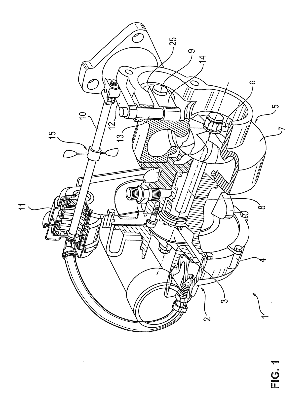
[0018]FIG. 1 shows an exhaust-gas turbocharger 1 in a schematically simplified, partially cut-away view. The exhaust-gas turbocharger 1 comprises a compressor 2 with a compressor wheel 3 and with a compressor housing 4. Furthermore, the exhaust-gas turbocharger 1 comprises a turbine 5 with a turbine wheel 6 which is accommodated in a turbine housing 7. The compressor wheel 3 is connected to the turbine wheel 6 by way of a shaft 8.

[0019]As a result of the turbine wheel 6 being impinged on by a flow of exhaust gas, the shaft 8 is set in rotation and, as a result, charge air is compressed by means of the compressor 2.

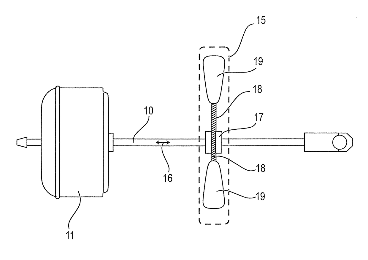
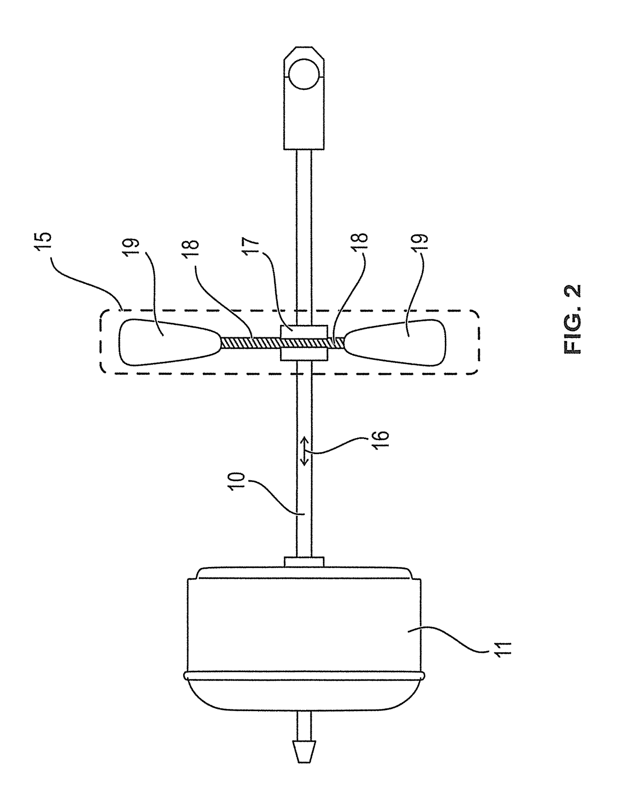
[0020]The illustration in FIG. 1 also shows an adjustment apparatus 9. The adjustment apparatus 9 is, in the first exemplary embodiment, in the form of a charge-pressure regulation means. In particular, the adjustment apparatus comprises a fla...


PUM


Abstract

An exhaust-gas turbocharger having a compressor with a compressor wheel, a turbine with a turbine wheel, a shaft on which the compressor wheel and the turbine wheel are arranged, a control rod for actuating an adjustment apparatus of the exhaust-gas turbocharger, and an actuator for moving the control rod. A damping apparatus with an elastic element is fixedly connected to the control rod and projects in two opposite directions from the control rod.

Description

BACKGROUND OF THE INVENTION[0001]Field of the Invention[0002]The invention relates to an exhaust-gas turbocharger.[0003]Description of the Related Art[0004]In exhaust-gas turbochargers, there are numerous adjustment apparatuses: One possible adjustment apparatus serves for the charge pressure regulating device. Said charge pressure regulating device may for example be in the form of a slide or a flap. A second example of an adjustment apparatus is a so-called variable turbine geometry. In this case, multiple vanes in the inlet region of the turbine are adjusted in order thereby to vary the geometry. The various adjustment apparatuses are in each case moved by means of a control rod and an actuator. Corresponding vibrations arise in the control rod, leading to increased wear of the adjoining components.[0005]It is an object of the present invention to provide an exhaust-gas turbocharger which, while being inexpensive to produce, can be operated with low maintenance and in an operatio...

Claims


Application Information

Patent Timeline
Patent Type & Authority Patents(United States)
IPC IPC(8): F02B33/00F02C9/16F02B37/24F02B37/18F02C6/12
CPCF02C6/12F02B37/186F02B37/24F02C9/16F05D2220/40Y02T10/144Y02T10/12
Inventor ZAHORANSKY, RADUZCHRISTMANN, RALF
Owner BORGWARNER INC
Learn More